
The circuit is powered by a 9-volt Krona battery. Coil L1 contains seven turns. copper wire on a mandrel 4 millimeters. The coils are slightly stretched and compressed to adjust the frequency of the transmitter. The actual range of this design is 80 MHz to 120 MHz. The antenna is just a piece of wire 50-100 cm. An analog signal from a microphone is sent to the audio input, then it follows a ULF based on a transistor. The output from the collector is connected to the second transistor. The scheme is easy to set up, which is why it is recommended for beginners.

The circuit of this radio bug is so simple that it starts working right away, unless of course you messed something up. The coil is made on a mandrel with a diameter of 0.5 centimeters and consists of five turns. winding wire with a diameter of 0.5 millimeters. Setting the radio transmitter consists of stretching or compressing the inductor coil. The bug operates in the standard FM range 88-108 MHz.

The antenna is a piece of multi-core installation wire 50 centimeters long. Almost any radio microphone will do. Transistor KT368, but you can use KT3102, KT315 and many others, see.
Using this circuit, you can broadcast music from your phone or MP3 player to your neighbors’ radio; to do this, we exclude the microphone and connect the player’s audio output through a trimming resistor, turning this circuit into an FM modulator.
FM radio transmitter |
The operation of the radio transmitter circuit is based on modulation of the FM band generator with an audio signal.

The FM band generator is made on the third transistor. Its operating point is set using a divider across resistances R10 and R11. In the collector circuit of this transistor there is a coil circuit L1. A capacitive divider is made on capacitors C4 and C5, which sets the amplitude and shape of the modulated signal. The actual frequency modulation is carried out by a BB105B varicap. Resistances R7 and R8 are voltage dividers, the signal from them is fed to the varicap.
The radio transmitter antenna is made of silver-plated wire with a diameter of 0.6 millimeters, which is wound on a paper sleeve with a diameter of 0.7 cm. Number of turns. - 38. Coil L1 consists of five vit. copper wire with a diameter of 0.8 millimeters. The coil is made on a paper sleeve with a diameter of 0.7 millimeters. in increments of 1.25. Bends from the first and second turns.
Next for consideration I suggest circuit of a miniature radio transmitter using a tunnel diode

The basis of this circuit is a high-frequency generator made on a tunnel diode. The tunnel diode is selected with a current consumption of no more than 10-15 mA (for example, you can use AI201A). The generator operates stably at a power source voltage of 1 V and above with the correct selection of the operating point using variable resistor R2. Choke Dr1 is wound directly on the MLT 0.25 resistor and contains approximately 200-300 turns. wire PEV 0.1. For prevention, it is better to lubricate the wound wire with glue. The inductance of the inductor should be about 100-200 μH. The oscillating circuit coil is frameless with a diameter of 0.8 cm and contains seven turns. PZV-1.0 wires with a winding length of 1.3 centimeters. Communication coil L2 is also frameless, but wound with PEV wire 0.35 millimeters, 3 turns, coil diameter 2.5 millimeters, winding length 0.4 cm. Coil L2 is inserted inside the coil of the oscillating circuit L1. Setting up the radio transmitter comes down to setting the operating point of the tunnel diode by adjusting the trimming resistor R2 until stable generation appears and adjusting the oscillation frequency with capacitor C4.
A piece of wire about a quarter wavelength long can be used as an antenna. The modulation depth is changed by changing the resistance of resistor R1. The signal from this radio transmitter is received on a regular TV. To minimize the design of the radio microphone, it is better to take a small-sized one and connect it directly to the high-frequency generator.
A possible diagram of such a radio transmitter is shown in the second figure. It uses a condenser microphone, which is an unfolded capacitor with two flat fixed electrodes, parallel to which a membrane is attached; it can be made of thin foil or metallized dielectric film.

The membrane must be electrically isolated from the stationary electrodes. Acting as a circuit element, a condenser microphone carries out frequency modulation. The radiation power of homemade radio microphones is a fraction of a milliwatt. And therefore their range of action is a maximum of tens of meters.

Operation of the circuit: the modulating voltage is removed from the MKE-3 microphone or a similar one and is supplied to the base of the transistor through capacitor C1. A master oscillator is built on VT1. Changing the mixing voltage at the emitter junction changes the capacitance of the base-emitter circuit, which is part of the oscillatory circuit of the master oscillator. This is how simple the frequency modulation of a radio transmitter occurs in this circuit.
Capacitor C4 is included in the feedback target of the capacitive three-point, being one of the arms of the divider C6a-C4, from which the feedback voltage is removed. The capacitance of capacitor C4 makes it possible to regulate the excitation level. To avoid the influence of the shunt resistor R2 in the emitter circuit of the transistor on the oscillatory circuit, a choke Dr1 is connected in series with the resistor R2, which prevents the passage of high-frequency currents. Its inductance is 20 μH.
Inductor L1 contains 7 turns of wire PEV 0.35, frameless, with a diameter of 0.3 cm. VT1-KT368, although KT3102 can be used
Radio transmitter powered by miniature battery circuit diagram |

The master oscillator is made on transistor VT1 type KT368, resistor R1 sets its operating mode. The oscillation frequency is set by the oscillatory circuit L1-C3 and the capacitance of the emitter junction of the transistor; in the collector circuit of the transistor, the load is another oscillatory circuit L2-C6, C7. Capacitor C5 can set the excitation level of the generator. A change in the capacitance of the emitter junction due to vibrations of the microphone changes the resonant frequency of the oscillating circuit, and frequency modulation appears.
Capacitor C1 is designed to filter high-frequency oscillations, and C7 can change the value of the carrier frequency. C8 - reduces the influence of disturbing factors on the generator oscillation frequency
The antenna can be made from a piece of copper wire 60 cm long. The length of the antenna can be reduced if an additional extension coil L3 is connected between it and the capacitor C8. All coils in this miniature radio transmitter circuit are frameless, 2.5 in diameter and wound turn to turn. Coil L1 has 8 turns, coil L2 has 6 turns, coil L3 has 15 turns. wires PEV 0.3.
When setting up the design, you need to obtain the maximum high-frequency signal by changing the inductance of the coils L1 and L2. By selecting capacitor C7, you can slightly change the value of the carrier frequency.

This circuit is just a single-stage VHF FM transmitter operating in the standard FM1 band. The output power of this circuit is approximately 20 mW, which allows the signal to be rebroadcast over 150 m. The device can operate reliably with a supply voltage of 4-5 V, but at the same time the transmission range decreases.
The amplified low-frequency voltage from transistor VT1 passes to the varicap VD2 - KV409A. Varicap VD1 is connected in series with trimming capacitor C8 in the emitter circuit of transistor VT2. The oscillation frequency of the master oscillator on VT2 type KT368 is set by the oscillatory circuit L1, C6, C7 and capacitance C8 and VD1.
Coil L1 is frameless, 8 mm in diameter, contains 6 turns. wires PEV 0.8. The radio transmitter is tuned by compressing or stretching turns L1 or adjusting capacitor C8.

The circuit provides a transmission range of about 100 m. The radio transmitting device consists of an RF generator on a VT2 transistor of type KT315, and a single-stage ULF on a VT1 transistor of type KT315. Instead of outdated KT315 transistors, it is better to use KT3102. Coil L1 is wound on a frame with a diameter of 0.7 centimeters and has a tuned 600NN ferrite core 12 millimeters long and contains 8 turns. PEV 0.15. Winding - turn to turn.
Choke Dr1 is wound on a resistor MTL-0.5 with a resistance of 100 kOhm. The inductor winding contains 80 turns of PEV 0.1. After adjusting the transmitter, the tuning coil core is filled with paraffin.

The radio transmitter consists of a single-stage ULF amplifier and a single-stage HF generator. The carrier frequency is determined by parameters C4, L1, C5 and transition capacitance VT2. The modulating amplifier is assembled on VT1 type KT315.
The signal from the generator enters the antenna, which is made from a piece of mounting wire 10 cm long. Coil L1 is frameless, wound on a mandrel with a diameter of 3 mm and contains 4 turns of 0.6 mm PEV wire, a winding pitch of 2 millimeters. The transmission range is about 50-70 meters on the FM 2 band.
FM radio transmitter for FM1 and FM2 |

Circuit operation: Low-frequency oscillations from microphone M1 through capacitor C1 are supplied to the ULF on transistor VT1 type KT315. The amplified signal through the inductor Dr1 acts on the varicap VD1 type KV109A, which carries out frequency modulation of the radio signal. The HF generator is assembled on a transistor VT2 - KT315. Its frequency depends on the oscillatory circuit L1, C3, C4, C5, C6, VD1.
The RF signal is amplified by a power amplifier using a VT3 transistor, type KT361. It is galvanically connected to the master oscillator. The amplified RF signal is supplied to a U-shaped circuit, on elements C11, L2, C10.
Instead of varicap VD1 type KV109A, you can use KV102. Transistors can have any letter index. Transistors VT1 and VT2 can be replaced with KT3102, KT368, and transistor VT3 with KT326, KT3107, KT363.
Chokes Dr1 and Dr2 are wound on MLT 0.25 resistors with a resistance of more than 100 kOhm using PEV 0.1 wire, 60 turns each. Coils L1 and L2 are frameless, with a diameter of 5 mm. Coil L1 - 3 turns, coil L2 - 13 turns of PEV 0.3 wire.
The setting consists of setting the frequency of the master oscillator by changing the capacitance of the tuning capacitor. By stretching or compressing the turns of the L2 coil, we set the radio microphone to maximum power. The transmission range can reach 150-200 meters.
Radio transmitter with compact loop antenna |

This homemade radio transmitting structure is designed for the first FM range of 65-73 MHz with frequency modulation. Frequency modulation occurs due to changes in the capacitance of diodes VD1, VD2 under the influence of modulating voltage
The amplified signal enters the loop antenna, which is made in the form of a spiral with a copper wire length of 100 cm, wire diameter of at least 1 mm.
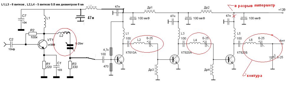
Radio transmitter components used in the circuit: Chokes Dr1, Dr2 - any, with an inductance of about 30 μH. Coils L1, L2, L3, L4, L5 are frameless, with a diameter of 10 mm. Coil L1 has 7 turns. L2 and L4 - 4 turns each. L3 and L5 - 9 turns each. All coils are wound with 0.8 mm PEV wire
With these parameters, and thanks to the loop antenna, the range of the eavesdropping device circuit reaches 150 meters.

Any power supply with a voltage from 5 to 15 volts is suitable to power this transmitter. In this circuit, the master oscillator is assembled on a VT2 field-effect transistor of the KP303 type. with a frequency determined by elements L1, C5, C3, VD2. FM occurs when the AF modulating voltage is supplied to the VD2 varicap of type KV109. The operating point of the varicap is set by resistor R2. The operating mode of the amplifier circuit is determined by resistor R4.
Chokes Dr1 and Dr2 - any with an inductance of 10-150 mH. L1 and L2 are wound on frames with a diameter of 5 mm with adjusted cores. Number of turns - 3.5 with a tap from the middle, winding pitch 1 mm, PEV wire 0.5 mm.
Setting up the radio microphone is carried out by setting the required generator frequency with capacitor C5 and obtaining maximum power using resistor R4 and capacitor C10

A powerful radio transmitter from FM to the standard FM range, when using a whip antenna, the range of action increases to a kilometer. The signal from microphone M1 goes to a two-stage ULF made on transistors VT1, VT2 type KT315. The ULF operating point is set through R5, R6, C3. The amplified low-frequency signal from the collector junction of transistor VT2 passes to varicap VD1 type KB109, connected to the emitter circuit of transistor VT3 type KT904. On which a single-stage RF generator is assembled. Circuit C8, C9, L1 is connected to its collector. The generator tuning frequency is regulated by the inductance of the coil L1 and capacitors C8, C5, VB1. Capacitor C9 in the circuit sets the feedback depth, and C10 matches the circuit with the external antenna.
Choke Dr1 type DPM 0.1 at 60 μH. Coil L1 is frameless, with an internal diameter of 8 mm, has 7 turns of 0.8 mm PEV wire.
The signal from the listening device can be caught on any VHF receiver. Supply voltage 9 V (KRONA type battery). The circuit consists of widely available and inexpensive radio elements.
The eavesdropping circuit consists of three parts, the first part is a microphone amplifier on transistor VT1, the second is an RF generator built on VT2, and the third part is an RF amplifier on the third transistor, the signal from which goes to the antenna.

Inductance L1 consists of 4 turns of copper wire with a diameter of 0.8 mm, the coil has a length of about 15 mm and a diameter of 4. Coil L2 consists of 6 turns of copper wire - 0.8 mm, the diameter of the coil is 4 mm. The antenna is made of copper conductor D = 0.8 mm, with a length of at least 75 cm. The C6L1 oscillating circuit is set to the operating frequency of the eavesdropping device, and the C9L2 circuit is set to the maximum range.
FM transmitter exciter with frequency synthesizer February 13th, 2012
The exciter performs the functions of receiving a stable, low-noise, spectrally pure radio signal modulated by an audio frequency signal supplied to the input from the audio path, and amplifying this RF signal to values suitable for driving the output power amplifier.
My synthesizer is built using a phase-locked loop (PLL) oscillator circuit that covers the FM range in 100 kHz steps.
A smooth range generator (VFO) can cover just a few megahertz with the required stability and acceptable noise without additional adjustment. Output power is adjustable from zero to 4 watts. The PLL feedback open detector turns off the transmitter if the synthesizer malfunctions.
The drawings show both sides of the board, so you can print them and align the necessary holes in the light. You should print the drawing in a mirror image to ensure that the areas where the copper remains are inked.
This board is soldered around the perimeter with strips of metal. It is better to do this before installing the parts.
This wiring diagram shows the arrangement of elements on the board. You can understand what is shown here using the circuit diagram. It's pretty simple. Be careful, one element of the circuit is NOT shown in the picture! It must be installed after, during setup, under the board! To make the process more fun and to give you a good understanding of the design, I will NOT tell you what the part is! You will recognize it after assembly, it will turn out to be superfluous! :-)
The drawings of the coils are quite close to their actual dimensions.
Shown here is the assembled exciter! Some explanations about the aluminum part in the area of the output transistor. I made it on my amateur lathe.
This is a rather complicated way to ensure thermal contact between the TO-5 transistor body and the heatsink! The simplest bracket seems to be quite suitable. My initial idea was to screw it to the chassis, or to the board around the board. But the circuit works so efficiently that the transistor does not need an additional heatsink! I did some testing and in the end I left everything as shown in the picture without adding anything.
Many parts are taken from decommissioned equipment. Including tuning capacitors and chokes. But it is quite possible to select a replacement from modern parts. Quartz from JAN Crystals. In order to drive it to a non-standard frequency of 6.4 MHz parallel resonance, a 30 pF capacitor with standard temperature stability is used.
The signal is taken from the output using a BNC connector. All other connections are made using feed-through capacitors. The structure is equipped with covers made of the same metal as the perimeter sides. These are nothing more than cut up coffee cans! Metal from the packaging of some types of chocolate or cakes is also suitable! (translator’s note: cans of domestic condensed milk made of beautiful tinned tin)
Setting up the circuit is simple. First, set all KPIs to the middle position and set the frequency with the switches. To do this, understand a simple principle: the lowest switch has a weight of 100 kHz, the second 200 kHz, the next 400 kHz, and so on, until the last one, which weighs all 12.8 MHz. The ninth switch adds 76.8 MHz, and the tenth adds 102.4 MHz. Before setting the switches to the desired position, decompose the frequency you need into binary components. Please note: the switch in the "on" position does NOT add weight to the total! For example, if you want to broadcast on 96.5 MHz, you would set switches 9, 8, 7, 3, and 1 to off and the others to on. The entire range that can be set by the synthesizer switches overlaps FM and even captures neighboring ones, but the circuit is designed to operate in the broadcast range.
Now you should apply 15V only to the supply pin of the main part of the circuit, connecting a voltmeter to the output of op-amp U3, and a frequency meter to the collector of transistor Q4. If you get the right frequency, you've caught your luck by the tail and won the lottery! Usually, the VFO hangs somewhere outside the range. If the voltmeter shows about 14 V, this means that the frequency is too low. If the reading is near zero, this indicates an excessively high frequency. The frequency meter should confirm this. You must drive the VFO into range. To do this, you can change both the capacitance C20 and the inductance L4. Usually a capacitor does not provide frequency adjustment over the entire range, and then all that remains is to wrinkle the coil. When you can set the VFO correctly, the PLL will lock into sync and you will get a stable output signal, which is what you need. Tighten L4 and C20 so that the voltmeter reads about 9 V. This voltage range produces the lowest level of varicap phase noise because the control voltage is much higher than the detected RF. Ideally, you would get that 9V in the center of the broadcast band. But this can be easily done later.
Now, using C12, set the exact frequency of the quartz oscillator, focusing on the readings of the frequency meter. It should show exactly the frequency previously set by the switches in the broadcast range.
Let's move on to the amplifier stages: Connect a 50 Ohm equivalent load and a power meter to the output and apply a few volts of power to the power amplifier's power pin. Adjust C28, C32, C37 and C38 for maximum output. If the capacitor adjustment range is not enough, remember L5, L7, L11, L10. Now increase the supply voltage and adjust the capacitances again. You should get 4-5W with a 15V supply.
To eliminate the microphone effect, after assembly and configuration, fill the VFO coil, and perhaps other stages, with beeswax or other suitable material. After this, it may be necessary to slightly adjust the contours again.
Now connect the audio path to the exciter. Apply an audio signal to the input, strictly controlling the level, and set the deviation to +/- 75 kHz with resistor R68. If you do not have a deviation meter, turn on the FM receiver, pick up local stations and set the equivalent reception volume of your transmitter. But this method has a noticeable error; it is still better to use the device.
If you need to change the transmission frequency, program it again with the switches, and then adjust the entire path, with the exception of C12, which only needs to be adjusted every few years due to aging of the quartz.
When using a compact antenna, this device provides a communication range of about 100 meters, and when using a full-size whip antenna - more than 600 meters. The transmitter circuit is shown in Fig.
The signal from the microphone goes to a low-frequency amplifier (transistors VT1, VT2) with direct connections. The amplified signal through filter R9, C4, R10 is fed to varicap VD1 type KV109, connected to the emitter circuit of transistor VT3 type KT904. The varicap bias voltage is set by the collector voltage of transistor VT2. The HF generator is made according to a common base circuit. The collector circuit of transistor VT3 includes circuit C8, C9, L1. The tuning frequency is determined by the inductance of the coil and capacitances C8, C5, VD1. Capacitor C9 sets the feedback depth, and C10 sets the matching with the antenna. A choke of any type with an inductance of about 60 μH. Coil L1 is frameless, with an internal diameter of 8 mm, has 7 turns of 0.8 mm PEV wire. The length of the full antenna is 0.75...1 meter. Transmitter power is about 200 mW. If such power is not needed, you can reduce it by using resistor R2 with a resistance of 50..100 kOhm and replacing the choke with a resistor of about 300 Ohm. In this case, the transistor can be replaced with KT368. Low power transmitter frequency stability is higher and battery life is increased.
High power radio transmitter without additional power amplifier
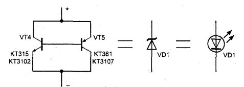
The proposed radio transmitter differs from previous devices in the design of the master oscillator, which makes it possible to obtain increased radiation power without the use of an additional power amplifier. The radio transmitter (Fig. 1) operates at a frequency of 27-28 MHz with amplitude modulation. The carrier frequency is stabilized by quartz, which allows you to increase the communication range when using a receiver with quartz frequency stabilization. The device is powered by a power source with a voltage of 3-4.5 V. The audio amplifier is made using a VT1 transistor, type KT315. To power the microphone and set the DC modes of transistors VT1, VT2, VT3, a parametric voltage stabilizer is used on resistor R2, LED VD1 and capacitor C1. A voltage of 1.2 V is supplied to an electret microphone with an amplifier Ml type MKE-3, "Sosna", etc. The audio frequency voltage from the microphone Ml through capacitor C2 is supplied to the base of transistor VT1. The DC operating mode of this transistor is set by resistor R1. The amplified audio frequency signal, removed from the collector load of transistor VT1 - resistor R3, is supplied through the capacitor SZ to the master oscillator, thereby carrying out amplitude modulation of the transmitter. The master oscillator of the transmitter is assembled on two transistors VT2 and VT3 of type KT315 and is a push-pull self-oscillator with quartz stabilization in the feedback circuit. The circuit, consisting of coil L1 and capacitor C5, is tuned to the frequency of the quartz resonator ZQ1. The circuit, consisting of coil L2 and capacitor C7, is designed to match the antenna and transmitter. The device uses MLT-0.125 resistors. Capacitors are used for voltages greater than 6.3 V. Transistor VT1 can be replaced with any pnp transistor, for example, KT3102, KT312. Transistors VT2, VT3 can be replaced with KT3102, KT368 with the same current transfer coefficient. A good result can be obtained by using the KR159NT1 microcircuit, which is a pair of identical transistors. The contour coils are wound on a frame with a diameter of 5 mm, which has a tuning core made of carbonyl iron with a diameter of 3.5 mm. The coils are wound in 1 mm increments. Coil L1 has 4+4 as the supporting element of the parametric voltage stabilizer circuit in Fig. 1 turn, coil L2 - 4 turns. Both coils are wound with PEV 0.5 wire. Choke Dr1 has an inductance of 20-50 μH. A wire about 1 m long is used as an antenna. One KBS-4.5 V flat battery or four elements of type A316, A336, A343 can be used as a power source. LED VD1 type AL307 can be replaced with any other or use an analogue of a low-voltage zener diode with a low stabilization current (Fig. 2.). Setting up the transmitter begins with setting the DC modes of transistors VT2 and VT3. To do this, connect a milliammeter to the power circuit break at point A and select the resistance value of resistor R4 such that the current is 40 mA. Configuration of circuits L1, L2, C5, C7 is carried out according to the maximum RF radiation. Moreover, they roughly tune the operating frequency with capacitors, or more precisely, with the coil core. The trimmer of coils L1, L2 should be located at a distance of no more than 3 mm from the center of the coils, since in its extreme positions generation can be disrupted due to a violation of the symmetry of the arms of transistors VT2, VT3.

5 kilometer transmitter:

20 watt power amplifier
Transmitters with analog frequency stabilization. -> 4 Watt FM Transmitter

This is a small but quite powerful FM transmitter that has three RF stages connected to an audio preamplifier for better modulation. Its output power is 4 watts and it is powered by 12-18 volts DC, making it portable. This is the perfect project for beginners who want to dive into the exciting world of FM radio broadcasting and want a diagram that will form the basis for experimenting with it.
Technical Specifications - Characteristics
Modulation type:......FM
Frequency range: ...... 88-108 MHz
Operating voltage: ..... 12-18 VDC
Maximum current: ....... 450 mA
Output power: ....... 4 W

How it works As already mentioned, the transmitted signal is frequency modulated (FM), which means that the amplitude of the carrier remains constant, and its frequency changes in accordance with the change in the amplitude of the audio signal. When the amplitude of the input signal increases (i.e., during positive half-cycles), the carrier frequency also increases, on the other hand, when the amplitude of the input signal decreases (negative half-cycles or no signal), the carrier frequency decreases accordingly. In Figure 1 you can see a graphical representation of frequency modulation as it appears on the oscilloscope screen, along with the modulating audio signal. The transmitter's outgoing frequency varies from 88 to 108 MHz, i.e. FM band used for radio broadcasting. The circuit, as we have already said, consists of four cascades. Three RF stages and an audio preamp for modulation. The first RF stage is a generator, it is built on the basis of TR1. The generator frequency is controlled by the LC circuit L1-C15. C7 is there to ensure oscillation continues and C8 regulates the capacitive coupling between the oscillator and the next RF stage, which is the amplifier. The amplifier is based on TR2, which operates in class C, the input of which is adjusted by changing the values of C10 L4. From the output of this last stage, which is adjusted by changing the values of L3-C12, the output signal is removed, which comes to the antenna through the configured chain L5-C11. The preamplifier circuit is very simple, it is based on TR4. Input sensitivity is adjustable to allow the transmitter to be used with a variety of input signals and is dependent on the value of VR1. The transmitter can be modulated directly from a piezoelectric microphone, small cassette recorder, etc. And of course you can use an audio mixer for more professional results.

Design. First, let us cover some basics of assembling electronic circuits on a printed circuit board. The board is made of thin insulating reinforced material with a thin layer of conductive copper, the conductive layer is shaped to create the necessary connections between the various components on the board. It is highly advisable to use a properly designed printed circuit board, as this significantly speeds up assembly and reduces the likelihood of making mistakes. Plus, the board kit comes with pre-drilled holes and component outlines with their designations on the component side to make assembly easier. To protect the board from oxidation during storage and ensure that you receive it in great shape, it is tinned during production and coated with a special varnish that protects it from oxidation and makes soldering easier. Soldering the components is the only way to assemble the circuit, and by the way, your success or failure largely depends on it. It's not too difficult and if you stick to some rules you shouldn't have any problems. The soldering iron you use should be lightweight and its power should not exceed 25 watts. The tip should be thin and clean all the time. There are very convenient specially made sponges for this purpose, which are kept damp, and from time to time you can wipe the hot sting on them to remove any residue that tends to accumulate on it. DO NOT use a file or sandpaper to sand a dirty or worn tip. If the tip cannot be cleaned, replace it. There are many different types of solder available in stores, and you should choose a good quality solder that contains flux to ensure a perfect connection every time. DO NOT use soldering flux other than what is already in the solder. Too much flux can cause many problems and is one of the main causes of circuit malfunction. If you do have to use additional flux, as is the case when you need to tin copper wires, clean it thoroughly after finishing the job. To properly and properly solder components, you should do the following: - Clean the component feet using a small piece of sandpaper. Bend them at the appropriate distance from the component body and insert it into the board in its place. - Sometimes you may encounter components with legs that are larger than usual, they are too thick to fit into the holes on the PCB. In this case, use a mini drill to widen the holes. - Do not make the holes too large, as this will make soldering difficult later. - Take a hot soldering iron and place the tip on the leg of the component while holding the tip of the solder wire at the point where the leg comes out of the board. The tip should touch the leg slightly above the board. - When the solder begins to melt and flow, wait until it evenly covers the entire area around the hole and the flux boils and comes out under the solder. The entire operation should not take more than 5 seconds. Remove the soldering iron and allow the solder to cool on its own without blowing on it or moving the component. If done correctly, the joint surface should have a shiny, metallic tip, and the boundaries should end evenly on the component leg and board trace. If the solder looks awkward, abnormal, or blobby, then you have made a bad connection and should remove the solder (Use a pump or soldering wick) and repeat the steps. - Be careful not to overheat the traces, as they are very easy to separate from the board and tear. - When soldering sensitive components, it is a good practice to hold the pin on the component side with tweezers to dissipate heat that could damage the component. - Make sure you don't use more solder than necessary, as you may short circuit adjacent tracks, especially if they are very close to each other. - When finished, cut off any protruding component legs and thoroughly clean the board with an appropriate solvent to remove any flux remaining on the board. This is an RF project, which requires even more care during soldering, as carelessness during assembly can result in low or no power output, poor stability, and other problems. Make sure you follow the basic rules of electronic circuit assembly described above and double check everything before moving on to the next step. All components are clearly marked on the side of the board elements, and you should have no problems identifying their location and installation. First, solder all the leads, and then the coils, being careful not to deform them, then the chokes, resistors, capacitors, and finally the electrolytes and trimmers. Check whether the electrolytes are installed correctly, in accordance with their polarity, and whether the trimmers are overheated during soldering. At this point you need to stop to check the work done, and if everything is in order, solder the transistors in their places, being careful not to overheat them, since they are the most sensitive of all the components used in this project. The audio signal is supplied to points 1 (ground) and 2 (signal), power is supplied to points 3 (-) and 4 (+), the antenna is connected to points 5 (ground) and 6 (signal). As we said, the signal you will use for modulation can come from a preamp or mixer, or in the case where you want to modulate the carrier with your voice, you can use the piezoelectric microphone that comes with the kit. (The quality of this microphone is not so high, but it is suitable if you are only interested in speech.) As an antenna, you can use an open dipole or Ground Plane (for the diagram of this antenna, see the figure). Before you start using or changing the operating frequency, you should perform a procedure called setup and described below.

Parts List
R1 = 220K
R2 = 4.7K
R3 = R4 = 10K
R5 = 82 Ohm
R = 150Ohm 1/2W x2 *
VR1 = 22K trimmer
C1 = C2 = 4.7uF 25V electrolyte
C3=C13=4.7nF ceramic
C4=C14=1nF ceramic
C5=C6=470pF ceramic
C7 = 11pF ceramic
C8 = 3-10pF trimmer
C9 = C12 = 7-35pF trimmer
C10 = C11 = 10-60pF trimmer
C15 = 4-20pF trimmer
C16 = 22nF ceramic *
L1 = 4 turns of silver-plated wire on a 5.5mm mandrel
L2 = 6 turns of silver-plated wire on a 5.5mm mandrel
L3 = 3 turns of silver plated wire on a 5.5mm mandrel
L4 = etched on board
L5 = 5 turns of silver plated wire on a 7.5mm mandrel
RFC1=RFC2=RFC3= VK200 RFC tsok
TR1 = TR2 = 2N2219 NPN
TR3 = 2N3553 NPN
TR4 = BC547/BC548 NPN
D1 = 1N4148 diode*
MIC = crystal microphone
Attention: parts marked * are used to configure the transmitter if you do not have a stationary wave bridge.
Settings
If you expect your transmitter to deliver maximum power at all times, you need to properly configure all 3 RF stages to ensure that power flows between them in the best possible way. There are two ways to do this, and which way to follow depends on whether you have an SWR meter. If you have an SWR meter, then turn on the transmitter, with the SWR meter connected in series with the antenna, and turn C15 to tune the transmitter to the frequency you have selected for broadcasting. Then adjust trimmers C8,9,10,12 and 11 until you achieve maximum power output on the SWR meter. For those who do not have an SWR meter, there is another method that gives good results. You just need to assemble a small diagram, fig. in Fig. 2, which connects to the output of the transmitter, you connect your multitester, which has a suitable marked volt scale, to its input (on C16). You adjust the C15 to the desired frequency, and then adjust the other trimmers in the same order as described above, up to the maximum value on the multitester. The disadvantage of this method is that you cannot adjust the transmitter with an antenna connected at the output, which may be necessary with a slight adjustment of C11 and C12 for the best antenna matching. Remember to adjust your transmitter every time you change antenna or operating frequency. ATTENTION: In each transmitter, in addition to the fundamental frequency, there are various harmonics, usually having a short range. To make sure you're not tuning into one of them, tune as far away from your receiver as possible, or use a spectrum analyzer to look at the output spectrum and make sure you're tuning the transmitter to the correct frequency.
ATTENTION
If the device does not work. - Check the device for poor connections, shorted adjacent tracks, or flux residue, which are usually the cause of the problem. - Check again all external connections going to and from the circuit, there may be an error in them. - Check whether all components are installed and in their places. - Make sure that all polarity components are installed correctly. - Make sure that the supply voltage is the correct value and is supplied to the circuit in the correct location. - Check the circuit for faulty or damaged components.

10 W transmitter
Scheme 1 (27 MHz):

Q1 KT904 on a radiator with an area of 600 cm^2
L1 - diameter 15 mm on a ceramic frame. 5 turns of silver wire with a diameter of 1 mm, winding length - 20 mm, tap from the 2nd turn, counting from the grounded wire.
L3 - frameless, on an 8 mm frame, contains 11 turns of PEV-2 with a diameter of 1 mm.
L2 (choke) type DMM-2.4 (20 µH)
C1, C5, C6 - with air dielectric.
L3 - frameless, on an 8 mm frame, contains 8 (6 by 94 MHz) PEV-2 turns with a diameter of 1 mm. Consists of 2 halves.
L4 - on the same frame and with the same wire, located between the 2 halves of L3 and contains 2-3 turns
Circuit 3 (Frequency modulator):
Q1 KT315
D1, D2 - varicaps KV102D or diodes D220.
VM1 - electret microphone MKE-3
Description and setup: Select one of 2 high-frequency circuits (depending on the receiver) and connect it to the modulator at point A. Next, as a load, connect 2 lamps 6.3 V (0.22 A) connected in series to the antenna and the common wire . Connect the 5 V power. Disconnect circuit L1, C1, and instead apply a signal from the VHF generator to the input. Check the frequency of the output signal with a wave meter (if it is not there or it is not the same as from the generator, adjust the capacitors and coils of the output circuit). Next, connect circuit L1, C1 and increase the supply voltage. Self-generation should occur already at 5 V (if it does not occur, move the emitter along the coil by 0.5...2 turns) - a current of 250 mA. Do not raise the voltage above 20V (current 750 mA, power 8...10 W). Next, adjust all the circuits, checking the frequency with a wave meter. When mounting (mounted, directly on the radiator), the leads of the parts should be as short as possible, capacitors with the appropriate TKE should be used, and the coils should be wound tightly. Only then will you get good frequency stability, otherwise it will “float” up to 500 Hz. The frequency modulator is adjusted by selecting R1 when the voltage on the collector of Q1 becomes equal to half the supply voltage. It may also be necessary to connect point A to part of the L1 turns.
This FM transmitter is built on the basis of a varicap generator and a two-stage power amplifier. With a good antenna - for example a dipole located high enough, the transmitter has a very good range - about a kilometer, maximum range - up to 5 km. The circuit diagram is not at all complicated - with a little experience you can assemble it with your own hands in an evening. A thumbnail image is shown.
![]()
![]()
To adjust for maximum radiation, connect a 6 V / 0.1 A light bulb instead of an antenna. First of all, use resistor R1 to tune to the desired frequency, you can adjust the inductance of coil L1 if necessary. Then use trimmer capacitors C18 and C19 to achieve maximum power (bright lamp light). And only then you can connect the antenna and audio signal to the input of the radio transmitter. Adjust R2 so that the sound is loud enough and high quality, as on other FM radio stations.
![]()
![]()
The varicap can be replaced with a domestic one, which is installed in SK-V TV modules. For example KV109 or KV104. Transistor BFR96 - KT610. The rest are KT368. Further increase in range is possible with additional .
The first experience in radio broadcasting can be obtained by building a VHF broadcast transmitter. With its help, you can carry out musical and thematic broadcasts in small villages, recreation areas, beaches and other places where VHF broadcasting is not carried out or its reception is difficult. In order to simplify the design, a VHF transmitter can be built on just one vacuum tube.
A schematic diagram of a VHF transmitter for small radio broadcasting areas is shown in Fig. 28.1. The transmitter consists of a push-pull high-frequency generator on two triodes that make up the VL1 lamp.
Rice. 28.1. Schematic diagram of a VHF transmitter for small radio broadcasting areas
The transmitter modulator is made on a varicap VD1. To power the transmitter, any power supply can be used that provides two output voltages: constant 250 V to power the anode circuits and alternating 6.3 for the lamp filament. The transmitter is based on a circuit that has been well tested and has long been known in radio engineering.
This transmitter circuit allows you to receive a signal close to the VHF FM broadcast standard. The transmitter uses contour modulation, as it allows you to obtain high quality performance with a small number of radio components. The audio frequency signal from a microphone or tape recorder (from the additional loudspeaker sockets) is fed to the input of the transmitter XS1, from where through a transformer to the varicap VD1. As a result, the capacitance of the varicap VD1 changes and the carrier signal is modulated. The resulting electromagnetic oscillations are emitted by the antenna of the WA1 transmitter into space, which are received by the antennas of VHF radio receivers. This transmitter operates on one of the fixed frequencies lying in the range 90... 100 MHz. A more precise frequency of the transmitter's radio waves is established by changing the capacitance of capacitor C7.
In principle, the transmitter can be tuned to any VHF frequency; you just need to change the parameters of the LI, C7 circuit accordingly. The transmitter uses a 2.1 m long whip antenna located at a height of 3...4 m. The antenna is a duralumin or copper tube with a diameter of at least 18 mm.
Details
The transmitter uses a 6NZP series finger lamp and a high-frequency double triode. Resistors R1...R4 type MLT-0.5 with a resistance tolerance of ±10%, resistors R5, R6 type MLT-2 with a resistance tolerance of ±10%. Variable resistor R7 type SPZ-ZOv. Capacitors: C1, C2, C5, C6, SYU type KD-2; SZ, S4, S7 - KT-1, S8, S9 - BM-2; SP, S12 - BMT-2, and S13 - K50-12. The D902 varicap indicated in the diagram can be replaced with a more advanced one, for example, KV 109V or KV109G. When using other types of radio components, it should be borne in mind that they must be designed for a voltage of at least 300 V.
The transmitter loop coils L1...L3 are frameless and wound with 01 mm copper wire on a 010 mm mandrel. Coil L1 has 7 turns with a tap from the middle, and L2, L3 - 2 turns each. When mounting coils on the board, coils L2 and L3 are placed at a distance of 2 mm from each end of coil L1. The axes of the coils L1...L3 must lie on the same straight line. Choke L4 is wound with 00.4 mm enameled wire turn to turn on a 04 mm ferrite rod of grade 600 NN. Choke L5 contains 8 turns of PEL wire 01.2 mm, wound turn to turn on a mandrel 010 mm. As transformer T1, you can use the output transformer from any radio receiver or subscriber speaker. The high-resistance winding (containing a large number of turns of wire) of the transformer is connected to resistors R1 and R2. This transmitter design uses a transformer from the subscriber loudspeaker.
Most of the transmitter parts are mounted on a printed circuit board measuring 107x76 mm made of foil fiberglass 2 mm thick (Fig. 28.2). When installing the lamp socket, its petals are bent and soldered directly to the printed tracks. Parts L4, C14, R6, C13 are mounted using hinged mounting. After installation, the board along with the power supply is placed in a metal case. A variable resistor R7 is mounted on the front panel of the case, and in its upper part there is a connector for connecting an antenna. Transformer T1 should be located near resistor R7. A metal screen is installed between the power supply and the transmitter board. To connect the antenna to the transmitter, a cable of type RK-1 is used; you can also use cables of type RK-49 or RK-75.
The transmitter, assembled from serviceable parts, starts working immediately when the power is turned on. By rotating the axis of the variable resistor R7, the modulation depth is set at which there is no distortion and the modulation has sufficient depth.

Rice. 28.2. Printed circuit board and installation of VHF transmitter parts on it for small radio broadcasting areas
Literature: V.M. Pestrikov. Encyclopedia of amateur radio.


