It is difficult for any radio amateur to imagine his laboratory without such an important measuring instrument as an oscilloscope. And, indeed, without a special tool that allows you to analyze and measure the signals acting in the circuit, repairing most modern electronic devices is impossible.
On the other hand, the cost of these devices often exceeds the budgetary capabilities of the average consumer, which forces him to look for alternative options or make an oscilloscope with his own hands.
You can avoid purchasing expensive electronic products in the following cases:
Each of the options listed above, which allow you to make an oscilloscope with your own hands, is not always applicable. To fully work with self-assembled attachments and modules, the following prerequisites must be met:
Thus, an oscilloscope from a sound card, in particular, does not allow measuring oscillatory processes with frequencies outside its operating range (20 Hz-20 kHz). And to make a USB set-top box for a PC, you will need some experience in assembling and configuring complex electronic devices (as when connecting to a regular tablet).
Note! The option in which it is possible to make an oscilloscope from a laptop or tablet using the simplest approach comes down to the first case, which involves the use of a built-in circuit breaker.
Let's look at how each of the above methods is implemented in practice.
To implement this method of obtaining an image, you will need to make a small-sized attachment, consisting of only a few electronic components accessible to everyone. Its diagram can be found in the picture below.

The main purpose of such an electronic chain is to ensure the safe entry of the external signal under study to the input of the built-in sound card, which has its “own” analog-to-digital converter (ADC). The semiconductor diodes used in it guarantee that the signal amplitude is limited to a level of no more than 2 Volts, and a divider made of resistors connected in series allows voltages with large amplitude values to be supplied to the input.

A wire with a 3.5 mm plug at the mating end is soldered to the board with resistors and diodes on the output side, which is inserted into the circuit breaker socket called “Linear input”. The signal under study is supplied to the input terminals.
Important! The length of the connecting cord should be as short as possible to ensure minimal signal distortion at very low measured levels. It is recommended to use a two-core wire in a copper braid (screen) as such a connector.
Although the frequencies passed by such a limiter are in the low-frequency range, this precaution helps to improve the quality of transmission.
In addition to the technical equipment, before starting measurements, you should prepare the appropriate software. This means that you need to install on your PC one of the utilities designed specifically for obtaining an oscillogram image.

Thus, in just an hour or a little more it is possible to create conditions for research and analysis of electrical signals using a stationary PC (laptop).
In order to adapt a regular tablet for recording oscillograms, you can use the previously described method of connecting to an audio interface. In this case, certain difficulties are possible, since the tablet does not have a discrete line input for a microphone.
This problem can be solved as follows:
The advantages of this method of connecting to a computer are ease of implementation and low cost. Its disadvantages include the small range of measured frequencies, as well as the lack of a 100% guarantee of safety for the tablet.
These shortcomings can be overcome through the use of special electronic set-top boxes connected via a Bluetooth module or via a Wi-Fi channel.
Connection via Bluetooth is carried out using a separate gadget, which is a set-top box with an ADC microcontroller built into it. By using an independent information processing channel, it is possible to expand the bandwidth of the transmitted frequencies to 1 MHz; in this case, the input signal value can reach 10 Volts.
Additional Information. The range of action of such a self-made attachment can reach 10 meters.
However, not everyone is able to assemble such a converter device at home, which significantly limits the range of users. For anyone who is not ready to manufacture a set-top box on their own, there is an option to purchase a finished product, which has been available for free sale since 2010.
The above characteristics may suit a home mechanic who repairs not very complex low-frequency equipment. For more labor-intensive repair operations, professional converters with a bandwidth of up to 100 MHz may be required. These capabilities can be provided by a Wi-Fi channel, since the speed of the data exchange protocol in this case is incomparably higher than in Bluetooth.
The option of transmitting digital data using this protocol significantly expands the throughput of the measuring device. Set-top boxes that work on this principle and are freely sold are not inferior in their characteristics to some examples of classical oscilloscopes. However, their cost is also far from being considered acceptable for users with average incomes.
In conclusion, we note that taking into account the above limitations, the Wi-Fi connection option is also suitable only for a limited number of users. For those who decide to abandon this method, we advise you to try to assemble a digital oscilloscope that provides the same characteristics, but by connecting to a USB input.
This option is also very difficult to implement, so for those who are not completely confident in their abilities, it would be wiser to purchase a ready-made USB set-top box that is commercially available.
Currently, it is difficult to keep up with the latest radio electronics technologies. A variety of electronic devices can now be modified to suit your taste from one to another. There would be desire and ability. Even from an old electronic clock you can make a simple tester for many electrical circuit parts, not to mention tablets and computers. Many radio amateurs and professionals often have to use precision electronic instruments, among which the oscilloscope is very popular. Such a good device is not cheap. Although making it yourself using a tablet and Android will not be difficult even for a radio amateur.
 For those who are not particularly familiar with the operation of an oscilloscope and its visual views, I will explain. This is a device (in the old version like a mini-TV, in the new version - a tablet design, etc.) that measures and tracks frequency fluctuations in the electrical network. In practice, it is widely used by many specialized laboratories and professional radio and television technicians. Since precise settings of many electrical appliances are made only with its help.
Its readings in electronic or paper form allow you to see sinusoidal waveforms. The frequency and intensity of this signal, in turn, allows determine the malfunction or incorrect assembly of the electrical circuit. Today we will look at a two-channel oscilloscope, which you can assemble with your own hands based on the existing circuits of a smartphone, tablet and the corresponding software.
The measured frequency must be audible to the human ear, and the signal level must not exceed standard microphone sound. In this case, you can assemble an Android-based oscilloscope with your own hands without additional modules. Disassembling the headset, on which there is a microphone. If you do not have this headset, you will need to purchase a 3.5 mm audio plug with four contacts. Solder the probes according to the connectors of your gadget.
Download software from the Market that will measure the frequency of the microphone input and draw a graph based on this signal. The presented options will be enough to choose the best one. After calibrating the application, the oscilloscope will be ready for use.

To stabilize the signal and expand the input voltage range, you can use an oscilloscope circuit for a tablet. It has been used for a long time and successfully to assemble devices for the computer.
For this purpose, KS 119 A zener diodes with resistors of 10 and 100 kOhm are used. The first resistor and zener diodes are connected in parallel. Second and more powerful resistor connected to the input of the electrical circuit. This expands the maximum voltage range. Ultimately, additional interference disappears and the voltage increases to 12 volts.
A special feature of the tablet oscilloscope is that it works directly with sound pulses and unnecessary interference (shielding) of the circuit and probes in this case will be undesirable.
To work with such a circuit, you will need a program that can draw graphs based on the incoming audio signal. Many such options can be easily found in the Market. With their help you can select additional calibration and achieve maximum accuracy for a professional oscilloscope from a tablet or other functional device.
 A wide range of frequencies using a separate gadget is achieved by its set-top box with an analog-to-digital converter, which provides signal transmission in digital version. Due to this, higher measurement accuracy is achieved. In practice, it is a portable display that accumulates information from individual devices.
Currently, with electronic progress, consoles appear in stores that perform the functions of an oscilloscope. They transmit a signal using a Bluetooth channel to a tablet or smartphone. Such an oscilloscope is an attachment, connected to tablet via Bluetooth has its own characteristics. The measured frequency limit of 1 MHz, the probe voltage of 10 V and the range of about 10 meters are not always sufficient for the professional range of work activities. In such cases, you can use an oscilloscope - a set-top box with data transmission using Wi-Fi.
Wi-Fi significantly expands the capabilities of measuring devices. This type of information exchange between the tablet and the set-top box is especially popular. This is not a fashion statement, but pure practicality. Since the measured information is transmitted without delay to the tablet, which instantly displays any graph on its monitor.
 A clear user menu allows you to quickly and easily navigate the controls and settings of the electronic device. A recording device allows you to reproduce and transmit information in real time and to all points for all participants in this process.
Usually, along with the purchased oscilloscope set-top box, a disk with software is supplied. These drivers and program You can quickly download it to your tablet or smartphone. If there is no such disk, find this data in the application store or search on the Internet on forums and specialized sites.
Assembling a USB oscilloscope will cost you only 250–300 rubles and you can make it yourself.

The advantages of this device are its low cost, mobility and small size. But, unfortunately, there are more significant disadvantages. These are low sampling rate, presence of a PC, low bandwidth and memory depth.
For professionals this electronic “toy” obviously won't do. And for beginner radio amateurs, this is a very good oscilloscope simulator for acquiring certain practical skills.
By developing her first virtual instrument, she created a new market and helped many developers evaluate the possibilities of using the personal computer as a test and measurement platform. The availability of a PC to every developer became a market driver at the time, allowing a PC or laptop to become the basis of an instrumentation platform with low-cost data acquisition hardware and software. Now, in addition to National Instruments, which has excelled in this area, there are many other small companies on the market offering USB data acquisition devices called USB/PC oscilloscopes.
But today, most electronics developers have smartphones, and it would be common for them to use their smartphone, if not as a test platform, then at least to display the data obtained. This opens up a new direction in the development of virtual devices.
The data acquisition hardware, combined with a computing platform, can be made very compact, smaller than a credit card.
This concept has given rise to two interesting virtual instruments available on the market today. We are talking about SmartScope from LabNation and Red Pitaya. Both projects are open source and developed based on Xilinx FPGAs. The signal frequency and amplitude displayed on the mobile phone can be changed using a conventional touch interface, eliminating the need for rotary knobs.
LabNation SmartScope
SmartScope costs about $200. Depending on the additional external peripherals included in the kit, the price may vary slightly, either down or up.
SmartScope can be powered through a USB cable connected to your smartphone or through an external USB power source. SmartScope can perform the functions of not only an oscilloscope, but also a logic analyzer and signal generator.
SmartScope supports a variety of operating systems, including Linux, iOS, Android and Windows. However, connecting to any of them may cause difficulties. SmartScope can be recognized if you install a jailbreak patch on your iOS device (iPhone and iPad). And in case of Android, you should check if your phone supports USB OTG. But with most of the latest Android phones, this shouldn't be a problem. Still, we strongly recommend that you check the details on the website.
Red Pitaya
Red Pitaya is more expensive, but it won't put you through the inconvenience that you might encounter when starting out with SmartScope. Although the Red Pitaya is similar to the SmartScope in most respects, it offers smartphone apps that can be downloaded from the cloud for specific applications. You can also develop your own applications. Red Pitaya is based on Xilinx Zynq FPGA, while SmartScope uses Xilinx's Spartan. The use of modern FPGAs makes reconfiguration of both devices as simple as possible. FPGA programmers can apply their skills to improve the performance of these devices.
Red Pitaya operates as a web server that can be accessed from any internet-connected computer or smartphone by entering the IP address in a web browser. Red Pitaya can be connected to the network either using a network cable or via Wi-Fi. A microUSB port is provided to power the device, as well as to connect it to another console. The system comes pre-installed with Linux OS, power supply, BNC connectors and probes. With its own DHCP configuration, setting up Red Pitaya is a breeze. There is also a manual setting option. The SD card supplied with the device contains all the necessary software, but downloading from your own card will not cause any difficulties.
The list of currently available applications includes an oscilloscope, signal generator, spectrum analyzer, LCR meter and more. They are as easy to download as any smartphone app; To do this you need to visit the website.
It is also possible to import data from MATLAB, or, conversely, export it to MATLAB.
Radio amateurs or students who want to create a laboratory on their own desk and do not need a bandwidth above 50 MHz should not purchase expensive oscilloscopes.
The Red Pitaya is $200 more expensive than the Smartscope, which is approximately $370-$470.
On the website http://www.semifluid.com I found a very simple solution for creating a digital computer oscilloscope. The device is based on an eight-bit PIC12F675 processor.
The processor operates at a frequency of 20 MHz. The microcontroller continuously measures the input voltage, converts it, and sends a digital value to the computer's serial port. The serial port baud rate is 115 kBit and, as shown in the following figure, data is scanned and sent at a rate of about 7.5 kHz (134 µs).
Device diagram

The basis of the circuit is the PIC12F675 microcontroller (U2 chip) which operates at a clock frequency of 20 MHz of the Y1 crystal. J1 is a standard power connector for connecting 9-12 V power, which is then stabilized at U1 to 5 V to power the processor.
After U2, a simple TTL level converter is added to the circuit with the RS232 serial port of a personal computer. It is built on the basis of transistor BC337 (Q1) and resistors R1 and R3. Input 5 of the microcontroller leads to switch S1. In its main position (1-2), the device switches to DC oscilloscope mode, which is capable of displaying a 0-5V input signal. In the second position - into AC oscilloscope mode. In this position, the maximum voltage is from -2.5 to +2.5 V. I used a 22000nF ceramic capacitor C6 to observe low frequencies without much distortion.
If necessary, you can add an additional input attenuator (splitter), or op-amp.
Software
In the original site mentioned above, a simple control program for Windows is also available. The program is written in Visual Basic.
The program starts immediately and waits for data to appear on the COM1 serial port. On the left, four sliders used to measure the period and voltage of the signal. Then there are on/off synchronization, fields for scaling or changing sample size values.
Installation
I did not make a printed circuit board, but mounted everything in a small plastic box using a surface-mounted system. The case must have holes for the RS232 connector of the switch, input jack, power jack.
Firmware for the processor is at the end of the article. The configuration bits (fuse) must be set as follows during programming:

Photo of my finished prototype


Below you can download the source, firmware and software for windows
| Designation | Type | Denomination | Quantity | Note | Shop | My notepad |
|---|---|---|---|---|---|---|
| U1 | Linear regulator | 1 | Search in Chip and Dip | To notepad | ||
| U2 | MK PIC 8-bit | 1 | 675-I/P | Search in Chip and Dip | To notepad | |
| Q1 | Bipolar transistor | 1 | Search in Chip and Dip | To notepad | ||
| C1, C2, C5 | Capacitor | 0.1 µF | 3 | Search in Chip and Dip | To notepad | |
| C3, C4 | Capacitor | 22 pF | 2 | Search in Chip and Dip | To notepad | |
| C6 | Capacitor | 22 µF | 1 | Search in Chip and Dip | To notepad | |
| R1, R3 | Resistor | 2 |
Nowadays, there is quite a lot of use of various measuring devices based on interaction with a personal computer. A significant advantage of their use is the ability to store the obtained values in a sufficiently large volume in the device’s memory, with their subsequent analysis.
Digital USB oscilloscope from computer, which we describe in this article, is one of the options for such amateur radio measuring instruments. It can be used as an oscilloscope and a device for recording electrical signals into the RAM and hard drive of a computer.
The circuit is not complicated and contains a minimum of components, resulting in a very compact device.
To exchange data between a USB oscilloscope and a personal computer, the Universal Serial Bus (USB) interface is used. This interface operates on the basis of the FT232BM (DD2) microcircuit from Future Technology Devices. It is an interface converter. The FT232BM chip can operate both in direct BitBang bit control mode (when using the D2XX driver) and in virtual COM port mode (when using the VCP driver).
The AD7495 (DD3) integrated circuit from Analog Devices is used as an ADC. It is nothing more than a 12-bit A/D converter with an internal voltage reference and a serial interface.
The AD7495 chip also contains a frequency synthesizer that determines the speed at which information will be exchanged between the FT232BM and the AD7495. To create the required communication protocol, the oscilloscope's USB software populates the USB output buffer with individual bit values for the SCLK and CS signals as shown in the following figure:

The measurement of one cycle is determined by a series of nine hundred and sixty successive transformations. The FT232BM chip, with a frequency determined by the built-in frequency synthesizer, sends electrical signals SCLK and CS, in parallel with the transmission of conversion data on the SDATA line. The 1st full conversion period of the FT232BM ADC, which sets the sampling frequency, corresponds to the duration of the period of sending 34 bytes of data issued by the DD2 chip (16 data bits + CS line pulse). Since the speed of data transfer of the FT232BM is determined by the frequency of the internal frequency synthesizer, to modify the sweep values you only need to change the values of the frequency synthesizer of the FT232BM chip.
The data received by the personal computer, after some processing (change of scale, zero adjustment) is displayed on the monitor screen in graphical form.
The signal under study is supplied to connector XS2. The OP747 operational amplifier is designed to match the input signals to the rest of the oscilloscope's USB circuitry.
On modules DA1.2 and DA1.3, a circuit is built to shift the bipolar input signal to the positive voltage zone. Since the internal reference voltage of the DD3 chip has a voltage of 2.5 volts, without using dividers, the input voltage coverage is -1.25..+1.25 V.
To be able to study signals that have negative polarity, with virtually unipolar power supply from the USB connector (a), a voltage converter DD1 is used, which generates a voltage of negative polarity to power the op-amp OP747. To protect the analog part of the oscilloscope from interference, components R5, L1, L2, C3, C7-C11 are used.
The uScpoe program is designed to display information on a computer monitor screen. Using this program, it becomes possible to visually evaluate the magnitude of the signal under study, as well as its shape in the form of an oscillogram.
![]()
The ms/div buttons are used to control the sweep of the oscilloscope. In the program, you can save the oscillogram and data to a file using the corresponding menu items. To virtually turn the oscilloscope on and off, use the Power ON/OF buttons. When you disconnect the oscilloscope circuit from the computer, the uScpoe program is automatically switched to OFF mode.
In electrical signal recording mode (recorder), the program creates a text file, the name of which can be specified in the following path: File->Choice data file. the data.txt file is initially generated. The files can then be imported into other applications (Excel, MathCAD) for further processing.
(3.0 Mb, downloaded: 3,610)
An oscilloscope is a very important instrument that is used in radio engineering laboratories involved in the manufacture and testing of many devices. But they can also be used in ordinary radio workshops. The main task of devices of this type is to detect and correct electronic circuits, debug their operation, and most importantly, to prevent problems in the manufacture of new circuits.
A significant drawback of oscilloscopes is their fairly high price. Therefore, not everyone can buy them. That's why the question arises, ? Although there are many known options for such manufacturing, each method involves one main element - a PC sound card. An adapter is attached to it, thanks to which the levels of the measured signals are coordinated.
Software
This device works thanks to a specific program. It transmits signals to the screen that are visualized. In this way, the measured pulses are converted. The choice of utilities is quite large, but not all of them can work consistently well.
The proven Osci program has gained the most popularity. Thanks to it, the oscilloscope works in normal mode. The program has an interface; a grid is installed on the screen, thanks to which you can measure the signal in length and amplitude. This mesh is special because it provides additional features. By choosing this program, there are a number of positive aspects that other programs cannot guarantee.
Technical data
To build an oscilloscope from a computer, you need to assemble a so-called voltage divider or attenuator. This device allows you to cover a wide range of measured voltages and protect the input port of the sound card from damage. Damage of this level occurs mainly due to high voltage.
Almost all audio cards have an input voltage of no more than 2 volts. An oscilloscope made from a computer is limited in the capabilities of the sound card. If we consider budget cards, then for them this figure remains at the level of 0.1 Hz - 20 kHz.
The voltage at its lower point is 1 mV. Such a low figure is explained by the limitation of background and noise levels. Upper voltage parameters – up to 500 volts. It is limited by the adapter parameters.
Advantages and disadvantages of oscilloscopes
No radio amateur can do without an oscilloscope. Although this device is sold at a fairly high price. But at the same time, it has both advantages and a number of disadvantages.
 The main advantage of an oscilloscope created with your own hands from a computer is its low price. That is, you will have to spend very little money on its re-equipment. But there are several disadvantages:
1. High sensitivity. The device responds to even low-level interference. This leads to large errors.
2. Sound signal amplitude up to 2V. The sound card input is not able to withstand more. Therefore, the sound card can fail quite quickly. However, this can be avoided.
3. Failure to continuously measure voltage. This, in fact, is not a significant drawback.
Creating an Oscilloscope
Since some oscilloscopes do not allow a signal higher than 2V, and for some it does not exceed 1V, you need to try to eliminate this problem, since such an amplitude is clearly not enough. The solution to the problem lies in increasing the limits that the adapter can handle. A modern program that ensures the operation of an oscilloscope allows one to achieve such measurement limits - 12.5 and 250 Volts.
If a signal whose amplitude is 250 Volts is not needed, then you can make an adapter with two channels. To do this, a protection is installed that controls the operation of the device, that is, it does not allow erroneous switching on if the voltage is quite high.
 To reduce the influence of external noise on the oscilloscope from the computer, it is necessary to place the board in a housing made of metal. Afterwards, a common wire is connected to this housing.
The process of setting up the sound card is accompanied by turning off the microphone gain. To do this, the volume on it is set to average or below average. Once all the work is done, you can start measuring the secondary processing pulses of the transformer. If everything is done correctly, then it will be able to display waveforms of even the lowest frequencies on the screen. Thanks to the installed program, you can easily determine the signal frequency level.
This is how it’s quite easy to make a modern device from a computer. The oscilloscope will produce waveforms that will help in work and experiments carried out in radio engineering and home laboratories.
Below is a project of a USB oscilloscope that you can assemble with your own hands. The capabilities of the USB oscilloscope are minimal, but for many amateur radio tasks it will do just fine. Also, the circuit of this USB oscilloscope can be used as a basis for building more serious circuits. The circuit is based on an Atmel Tiny45 microcontroller.
The oscilloscope has two analog inputs and is powered by a USB interface. One input is activated via a potentiometer, which allows you to reduce the input signal level.
The software for the tiny45 microcontroller is written in C and compiled using V-USB developed by Obdev, which implements HID devices on the microcontroller side.
The circuit does not use external quartz, but uses the USB frequency of 16.5 MHz in software. Naturally, you should not expect 1Gs/s sampling from this scheme.
The oscilloscope operates via USB via HID mode, which does not require the installation of any special drivers. Windows software is written using .NET C#. Using my program source code as a basis, you can expand the software as you need.

The circuit diagram of a USB oscilloscope is very simple!

List of used radioelements:
1 LED (any)
1 LED resistor, 220 to 470 ohms
2 x 68 Ohm resistors for USB D+ & D-lines
1 x 1.5K resistor for USB device detection
2 3.6V Zener diodes for USB level equalization
2 capacitors 100nF and 47uF
2 filter capacitors on analog inputs (from 10nF to 470nF), it is possible without them
1 or 2 potentiometers on analog inputs, to reduce the input voltage level (if necessary)
1 USB port
1 Atmel Tiny45-20 microcontroller.
| Designation | Type | Denomination | Quantity | Note | Shop | My notepad |
|---|---|---|---|---|---|---|
| R1, R5 | Resistor | 2 | Search in Chip and Dip | To notepad | ||
| R2 | Resistor | 1 | Search in Chip and Dip | To notepad | ||
| R3 | Resistor | 1 |
A cell phone has become a familiar item in everyday life, and many do not suspect that it is a fairly powerful computer (the processor clock speed of some phones exceeds 100 MHz) with a color screen, keyboard and good sound capabilities. Many phones are equipped with a serial port, which can be accessed programmatically from Java applications (midlets) with support for Java (J2ME platform) and MIDP 2.O. Through this port you can interact with various external devices, significantly expanding the standard set of functions of a cell phone. Among Siemens products, the MIDP 2.0 specification is supported by cell phones of the 65, 75 series (for example, M65, S75).
The proposed set-top box turns a cell phone into a kind of oscilloscope with an input impedance of 1 MOhm, a scan speed of 0.001... 1 s/div and a sensitivity of 0.5...50 V/div. The average value of the input signal (its constant component) is displayed in digital form
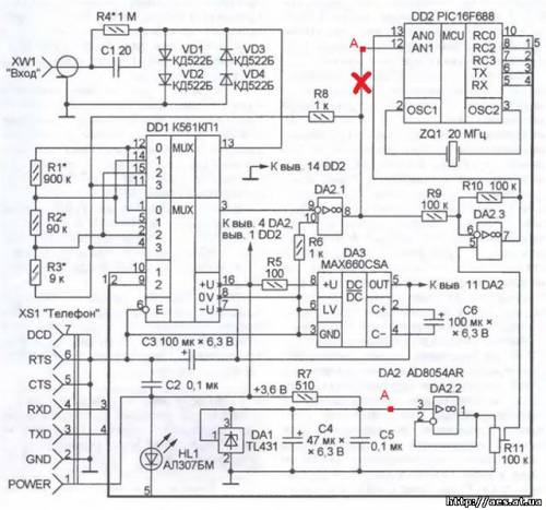
The set-top box, the diagram of which is shown in the figure, is controlled by a PIC16F688 (DD2) microcontroller, which includes ADC and serial port controller blocks. Unfortunately, the built-in ADC is quite slow, but for a low-frequency oscilloscope its speed (maximum sampling frequency is tens of kilohertz) is quite sufficient.
Unlike the signal levels adopted in the RS232 standard, the serial port of a cell phone is characterized by the usual levels for logic chips: log. 0 - about 0 V, log. 1 - at least 3.6 V. This simplifies pairing the phone with the MK, allowing you to connect them directly. The information exchange rate is chosen to be 9600 Baud. With a higher value, some models and copies of phones work unstably. The HL1 LED lights up when the packet is transferred from the microcontroller to the phone.
The set-top box receives power from the phone. Since pins 5-7 of the XS1 connector connected to the phone system connector are connected to a common wire, the phone controller believes that the DCA-500 data cable is connected to it and supplies 3.6 V from its battery to pin 1 of this connector. The negative voltage for powering the op-amp of the set-top box is obtained using a polarity converter DA3. The parallel voltage stabilizer DA1 and op-amp DA2.2, connected according to the repeater circuit, provides a reference voltage source of 2.5 V.
An electronic attenuator is assembled on the multiplexer DD1 and op-amp DA2.1, which allows you to change the sensitivity of the device depending on the code that the MK sets at the address inputs of the multiplexer (pins 9 and 10 of DD1). The multiplexer switches resistors R1-R3 in the feedback circuit of the op-amp, the resistance of which must accurately correspond to that indicated on the diagram. With code 00 at the address inputs of the multiplexer, the signal supplied to connector XW1 is transmitted to the output of op-amp DA2.1 without change. For other code values, the input signal is attenuated by a factor of 10, 100, or 1000. The last value is not used due to the insufficient electrical strength of resistor R4 and capacitor C1. Diodes VD1-VD4 limit the voltage at pin 13 of the multiplexer to 1.2 V (absolute value). The cascade on op-amp DA2.3 shifts the level of signals arriving at input AN1 of the MC so that the middle of the ADC scale corresponds to zero voltage at connector XW1.
The diagram has been corrected:
Working with a serial port in J2ME is organized through the CommConnection interface, and the port itself is named COM0. Before sending and receiving information, you must establish a connection using the Connection.open method. To avoid blocking the application during the exchange of information, all reading operations from and writing to the port are placed in a separate thread. More information about working with the serial port of a cell phone can be read in the online publication "Using Serial on Motorola J2ME handsets" -.
The MK of the set-top box, having received the control byte, sets the specified operating mode of the electronic attenuator, and then starts the ADC at a given frequency and writes the results of its operation to the internal buffer. When the buffer is full, the MK stops the ADC and transmits the synchronization byte to the cell phone, followed by the contents of the buffer. Having received this information, the phone displays it as a curve on the screen, calculates and displays the average voltage value.
If the oscilloscope operates in the automatic voltage scaling mode (the letter A is displayed on the screen), then if the average voltage value is close to zero or to the maximum permissible, the phone will generate a control byte with the attenuator position code changed in the appropriate direction. But this will affect the next measurement cycle.
The oscilloscope is controlled using a cell phone joystick: moving it vertically and horizontally changes the scale of the oscillogram along the corresponding axis. Enabling automatic scale selection and exiting the application is done through the menu.
The program for a cell phone is installed into it as a regular Java application. It is enough to copy the files osc.jar (compiled program) and osc.jad (its description) to the java/osc directory created in the phone memory. This is done using the special software included with the phone. After launching the application, the phone will ask questions about allowing access to the cellular port and accessory. You must answer yes to both.
The attachment was assembled by surface mounting on a breadboard; a printed one was not developed. Connector XS1 is special for connecting to a cell phone. Headsets and chargers are equipped with such connectors. Input connector XW1 - CP-50-73F or imported BNC series.
Instead of the TL431 chip, you can use KR142EN19, and instead of K561KP2 - CD4052. The AD8054 op amp will replace any other low current quad op amp, such as the MC3403.
Before starting to work with the oscilloscope, it is necessary to achieve a zero average voltage value displayed on the phone screen with the input of the set-top box shorted using trimming resistor R11.
Firmware for MK and application for phone - download
Photo from user andrej_m:


Regarding the seal: I did it quickly and for the parts that I had. diodes 1N4148; R1, R2, R3 - two in parallel; DA2-LM324.
STAMP WITHOUT CORRECTIONS (corrections are highlighted in red in the diagram above, you need to make them in the seal)


