The amplifier is made according to a circuit operating in AB mode; galvanic coupling of all stages made it possible to cover the entire amplifier with a broadband negative feedback loop. This ensured high stability of operation when the supply voltage and ambient temperature changed. The OS voltage is removed from the emitters of the output transistors and is supplied to the emitter VT1 through R9. The second OOS through R10 is introduced to reduce the influence of capacitor C5 on the output impedance of the amplifier. Which additionally influences the reduction of the SOI.
The base bias voltage of the output transistors is supplied to VD2 of the VT2 collector connected to the circuit. The nonlinearity of the current-voltage characteristic of the diode and its dependence on the ambient temperature is used to stabilize the output stage.
C4 prevents self-excitation of the UMZCH at HF, R11 prevents disruption of the operating mode in the event of an open load circuit.
Characteristics:
The power supply is not stabilized, KT3102G can be replaced with KT3102E or KT 342G. KT630 on KT807, it is installed on a small metal radiator. The output transistors have a radiator with an area of at least 100 sq. cm.
The adjustment comes down to balancing the flow dynamic characteristics by selecting the ratings R1 R2. In this case, the constant voltage at the emitters of the output transistors should be equal to half the power. In addition, we select VD2 so that the voltage across it drops 0.9V.
Literature - Radioconstructor 1999 - 07
Login using:
In Fig. shows the circuit of the simplest low-frequency amplifier, in which you can use a power source with a voltage of 4.5 or 9 V. With a load resistance of 10 Ohms and a supply voltage of 4.5 V, the rated output power is 70...80 mW, and when the voltage increases to 9 V, 120... 150 mW. The amplifier uses germanium low-power low-frequency...
According to IEC standards, in practice there are four ways to encode the nominal capacity. 1. 3-digit encoding The first two digits indicate the capacitance value in picofarads (pf), the last one indicates the number of zeros. When the capacitor has a capacitance of less than 10 pF, the last digit may be "9". For capacitances less than 1.0 pF the first ...
Today we have a useful homemade product for connoisseurs of good sound: a high-quality tube amplifier made by yourself
Hello!
I decided to assemble a push-pull tube amplifier (my hands were really itching) from the parts I had accumulated over a long time: housing, lamps, sockets for them, transformers, etc.
I must say that I got all this stuff for free (you mean free of charge) and the cost of my new project will be 0.00 hryvnia, and if I need to buy something in addition, I’ll buy it for rubles (since I started my project in Ukraine, and I’ll finish already in Russia).
I'll start the description with the body.

Once upon a time it was, apparently, a good amplifier from SANYO model DCA 411.
But I didn’t have a chance to listen to it because I got it in a terribly dirty and non-working state, it was dug up beyond repair and the burnt 110 V power supply (Japanese, probably) smoked all the insides. Instead of the original final stage microcircuits, there are some snot from Soviet transistors (this is a photo from the Internet of a good example). In short, I gutted it all out and began to think. So, I couldn’t think of anything better than stuffing a lamp there (there’s quite a lot of space there).

Decision is made. Now we need to decide on the scheme and details. I have a sufficient number of 6p3s and 6n9s lamps.


Due to the fact that I had already assembled a single-cycle amplifier for 6p3s, I wanted more power and, having rummaged through the Internet, I chose this push-pull amplifier circuit for 6p3s.
The diagram is taken from the website heavil.ru
I must say that the scheme is probably not the best, but due to its relative simplicity and availability of parts, I decided to stick with it. Output transformer (an important figure in the plot).
It was decided to use the “legendary” TS-180 as output transformers. Don’t throw stones right away (save them for the end of the article :)) I myself have deep doubts about this decision, but given my desire not to spend a penny on this project, I will continue.
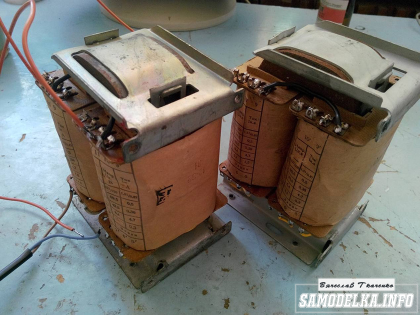
I connected the trance outputs for my case like this.
(8)—(7)(6)—(5)(2)—(1)(1′)—(2′)(5′)—(6′)(7′)—(8′) primary
(10)—(9)(9′)—(10′) secondary
anode voltage is applied to the connection of pins 1 and 1′, 8 and 8′ to the anodes of the lamps.
10 and 10′ per speaker. (I didn’t come up with this myself, I found it on the Internet). To dispel the fog of pessimism, I decided to check the frequency response of the transformer by eye. To do this, I quickly assembled such a stand.

In the photo there is a GZ-102 generator, a BEAG APT-100 amplifier (100V-100W), an S1-65 oscilloscope, a 4 Ohm load equivalent (100W), and the transformer itself. By the way, there is a .
I set it to 1000 Hz with a swing of 80 (approximately) volts and record the voltage on the oscilloscope screen (about 2 V). Next, I increase the frequency and wait until the voltage on the trance secondary starts to drop. I do the same thing in the direction of decreasing the frequency.
The result, I must say, pleased me: the frequency response is almost linear in the range from 30 Hz to 16 kHz, well, I thought it would be much worse. By the way, the BEAG APT-100 amplifier has a step-up transformer at the output and its frequency response may also not be ideal.
Now you can collect everything in a heap into a case with a clear conscience. There is an idea to do the installation and layout inside in the best traditions of so-called modding (minimum wires in sight) and it would also be nice to have LED backlighting like in industrial copies.
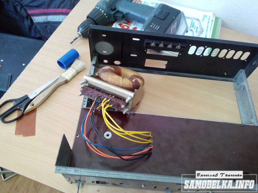
I'll start the assembly and at the same time describe it. The heart of the power supply (and of the entire amplifier, probably) will be the TST-143 toroidal transformer, which I once (4 years ago) tore out of some tube generator right as it was being taken to a landfill. Unfortunately, I didn’t manage to do anything else. It’s a pity for such a generator, but maybe it was still working or could have been repaired... Okay, I digress. Here he is my security officer.


Of course, I found a diagram for it on the Internet.

The rectifier will be on a diode bridge with a filter on the inductor for anode power. And 12 volts to power the backlight and anode voltage. This is the throttle I have.

Its inductance was 5 henry (according to the device), which is quite enough for good filtration. And the diode bridge was found like this.
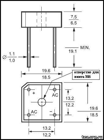
Its name is BR1010. (10 amps 1000 volts). I'm starting to cut out the amplifier. I think it will be something like this.

I mark and cut holes in the PCB for the sockets for the light bulbs.
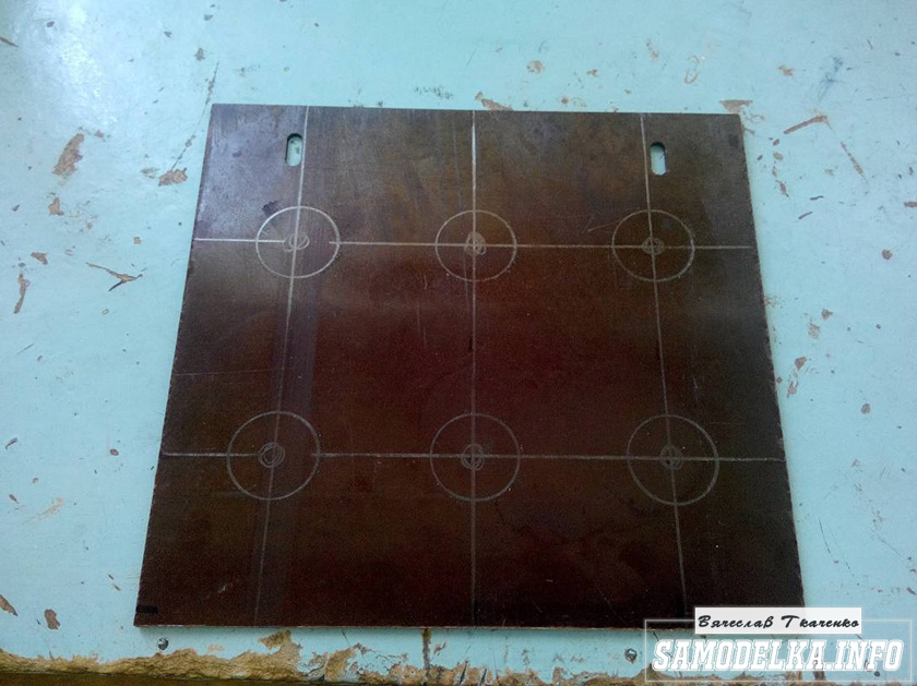
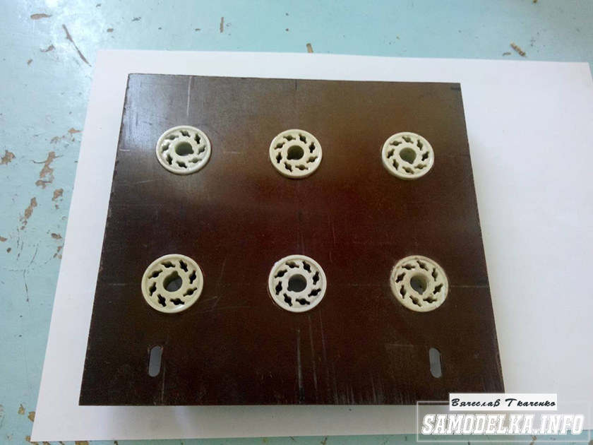


It turns out well :) I like everything so far.

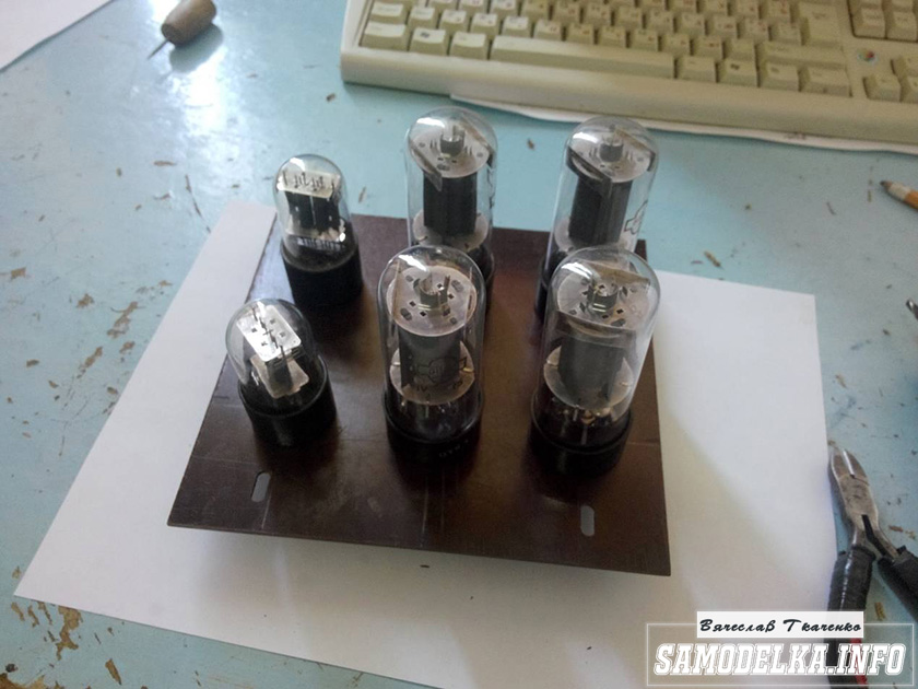
This way and that way. drill and saw :)

Something began to emerge.
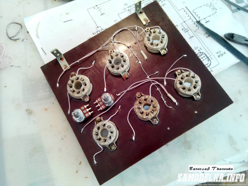
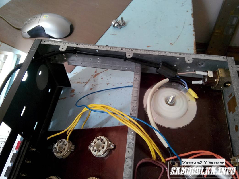
I found a fluoroplastic wire in old supplies and immediately all the alternatives and compromises regarding the wire for installation disappeared without a trace :) .


This is how the installation turned out. Everything seems to be “kosher”, the incandescence is intertwined, the ground is practically at one point. Should work.

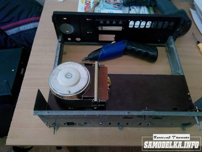
It's time to fence in food. After checking and testing all the output windings of the trans, I soldered all the necessary wires to it and began installing it according to the accepted plan.

As you know, in our life it’s not easy to go anywhere without improvised materials: this is how the Kinder Surprise container came in handy.

And a Nescafe lid and an old CD


I tore out the circuit boards of TVs and monitors. All containers are at least 400 volts (I know that I should have more, but I don’t want to buy them).
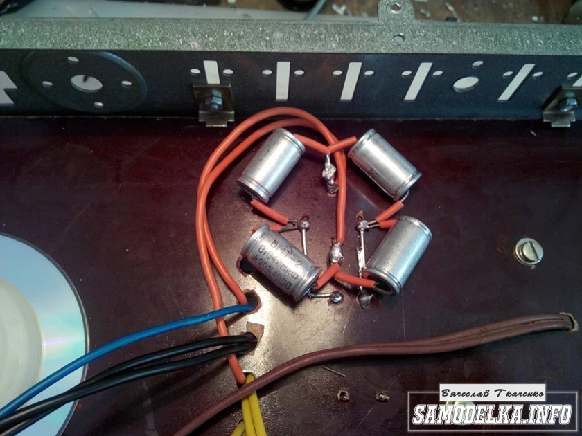
I bridge the bridge with containers (whatever were on hand, I’ll probably change them later)

It’s a bit much, but oh well, it will sag under load :)
I use the standard power switch from the amplifier (clear and soft).

We're done with that. It turned out well :)
To implement the backlight, an LED strip was purchased.

And installed in the housing as follows.


Now the glow of the amplifier will be visible during the daytime. To power the backlight, I will make a separate rectifier with a stabilizer on some KRKEN-like microcircuit (which I can find in the trash), from which I plan to power the anode voltage supply delay circuit.
Having rummaged through the bins of my homeland, I found this completely untouched thing.

This is a radio time relay designer for a photo enlarger.

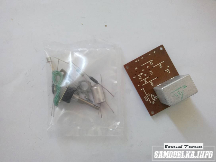
We collect, check, try on.


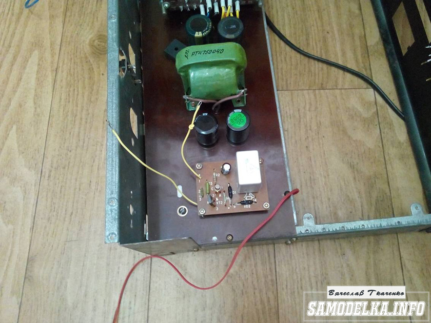
I set the response time to about 40 seconds, and replaced the variable resistor with a constant one. The matter is coming to an end. All that remains is to put everything together, install the face, indicators and regulators.
They say the sound quality can greatly depend on them. In short, I installed these
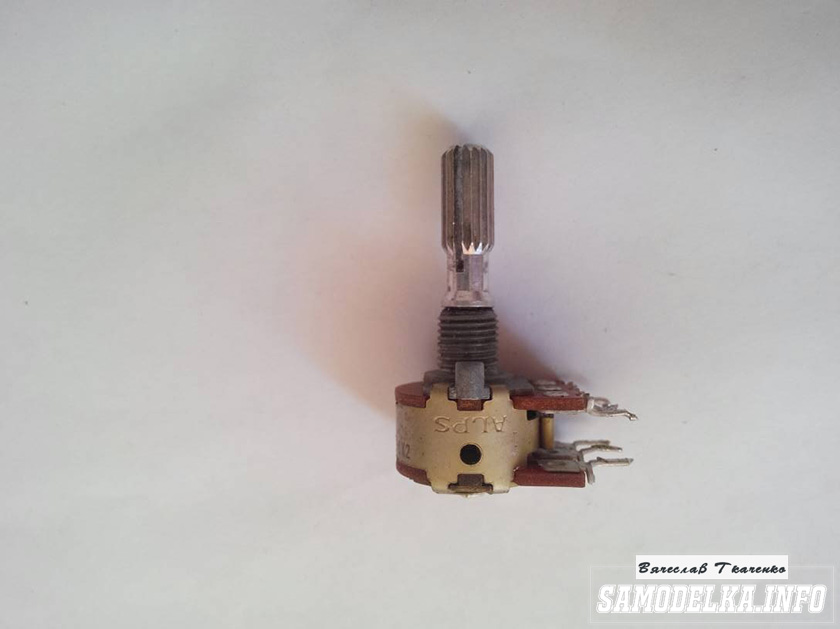
Dual 100 kOhm. Since I have two of them, I decided to parallel the pins, thereby obtaining 50 kOhm and increased resistance to wheezing :)
I used standard indicators, with standard backlighting

I mercilessly copied the connection diagram from the original board and used it as well.

This is what I ended up with.


When checking the power, the amplifier demonstrated an output voltage of 10 volts of an undistorted sine wave with a frequency of 1000 Hz into a 4 ohm load (25 watts) equally across channels, which was pleasing :)
When listening, the sound was crystal clear without background and dust, as they say, but too monitory, or what? beautiful, but flat.
I naively believed that he would play without timbres, but...
Using a software equalizer, we managed to get a very beautiful sound that everyone liked. Thank you all very much!!!
There were already publications on Habré about DIY tube amplifiers, which were very interesting to read. There is no doubt that their sound is wonderful, but for everyday use it is easier to use a device with transistors. Transistors are more convenient because they do not require warming up before operation and are more durable. And not everyone will risk starting a tube saga with anode potentials of 400 V, but transistor transformers of a couple of tens of volts are much safer and simply more accessible.
As a circuit for reproduction, I chose a circuit from John Linsley Hood from 1969, taking the author’s parameters based on the impedance of my 8 Ohm speakers.
The classic circuit from a British engineer, published almost 50 years ago, is still one of the most reproducible and receives extremely positive reviews. There are many explanations for this:
- the minimum number of elements simplifies installation. It is also believed that the simpler the design, the better the sound;
- despite the fact that there are two output transistors, they do not need to be sorted into complementary pairs;
- an output of 10 Watts is sufficient for ordinary human dwellings, and an input sensitivity of 0.5-1 Volts agrees very well with the output of most sound cards or players;
- class A - it is also class A in Africa, if we are talking about good sound. Comparison with other classes will be discussed below. 

It is possible with ordinary diodes or even ready-made bridges, but then they need to be bypassed with capacitors, and the voltage drop across them is greater. After the bridges there are CRC filters consisting of two 33,000 uF capacitors and a 0.75 Ohm resistor between them. If you take a smaller capacitance and a resistor, the CRC filter will become cheaper and heat up less, but the ripple will increase, which is not comme il faut. These parameters, IMHO, are reasonable from a price-effect point of view. A powerful cement resistor is needed for the filter; at a quiescent current of up to 2A, it will dissipate 3 W of heat, so it is better to take it with a margin of 5-10 W. For the remaining resistors in the circuit, 2 W of power will be quite enough.
Next we move on to the amplifier board itself. Online stores sell a lot of ready-made kits, but there are no fewer complaints about the quality of Chinese components or illiterate layouts on boards. Therefore, it is better to do it yourself, at your own discretion. I made both channels on a single breadboard so that I could later attach it to the bottom of the case. Running with test elements:

Everything except the output transistors Tr1/Tr2 is on the board itself. The output transistors are mounted on radiators, more on that below. The following remarks should be made to the author’s diagram from the original article:
Not everything needs to be soldered tightly at once. It is better to first set up resistors R1, R2 and R6 as trimmers, unsolder them after all adjustments, measure their resistance and solder the final constant resistors with the same resistance. The setup comes down to the following operations. First, using R6, it is set so that the voltage between X and zero is exactly half of the voltage +V and zero. In one of the channels I didn’t have enough 100 kOhm, so it’s better to take these trimmers with a reserve. Then, using R1 and R2 (maintaining their approximate ratio!) the quiescent current is set - we set the tester to measure direct current and measure this very current at the positive input point of the power supply. I had to significantly reduce the resistance of both resistors to obtain the required quiescent current. The quiescent current of an amplifier in class A is maximum and, in fact, in the absence of an input signal, all of it goes into thermal energy. For 8-ohm speakers, this current, according to the author's recommendation, should be 1.2 A at a voltage of 27 Volts, which means 32.4 Watts of heat per channel. Since setting the current can take several minutes, the output transistors must already be on cooling radiators, otherwise they will quickly overheat and die. Because they are mostly heated.
It is possible that, as an experiment, you will want to compare the sound of different transistors, so you can also leave the possibility of convenient replacement for them. I tried 2N3906, KT361 and BC557C at the input, there was a slight difference in favor of the latter. In the pre-weekend we tried KT630, BD139 and KT801, and settled on imported ones. Although all of the above transistors are very good, the difference may be rather subjective. At the output, I immediately installed 2N3055 (ST Microelectronics), since many people like them.
When adjusting and lowering the resistance of the amplifier, the low-frequency cutoff frequency may increase, so for the input capacitor it is better to use not 0.5 µF, but 1 or even 2 µF in a polymer film. There is still a Russian picture-scheme of an “Ultralinear Class A Amplifier” floating around the Internet, where this capacitor is generally proposed as 0.1 uF, which is fraught with a cutoff of all bass at 90 Hz:

They write that this circuit is not prone to self-excitation, but just in case, a Zobel circuit is placed between point X and ground: R 10 Ohm + C 0.1 μF.
- fuses, they can and should be installed both on the transformer and on the power input of the circuit.
- it would be very appropriate to use thermal paste for maximum contact between the transistor and the heatsink.
I made the body itself from plexiglass. We immediately order cut rectangles from glaziers, make the necessary holes for fastenings in them and paint them on the reverse side with black paint.


The plexiglass painted on the reverse side looks very beautiful. Now all that remains is to assemble everything and enjoy the music... oh yes, during final assembly it is also important to properly distribute the ground to minimize the background. As was discovered decades before us, C3 must be connected to the signal ground, i.e. to the minus of the input-input, and all other minuses can be sent to the “star” near the filter capacitors. If everything is done correctly, then you won’t be able to hear any background, even if you bring your ear to the speaker at maximum volume. Another “ground” feature that is typical for sound cards that are not galvanically isolated from the computer is interference from the motherboard, which can get through USB and RCA. Judging by the Internet, the problem occurs frequently: in the speakers you can hear the sounds of the HDD, printer, mouse and the background power supply of the system unit. In this case, the easiest way to break the ground loop is to cover the ground connection on the amplifier plug with electrical tape. There is nothing to fear here, because... There will be a second ground loop through the computer.
I didn’t make a volume control on the amplifier, because I couldn’t get any high-quality ALPS, and I didn’t like the rustling of Chinese potentiometers. Instead, a regular 47 kOhm resistor was installed between ground and the input signal. Moreover, the regulator on an external sound card is always at hand, and every program also has a slider. Only the vinyl player does not have a volume control, so to listen to it I attached an external potentiometer to the connecting cable.

For several decades now, "QUAD-405" has been one of the most famous amplifiers of the highest quality. With the use of innovations born of technology, its parameters have been repeatedly improved. We'll take a look at its modified version, which focuses on increasing power.
The purpose of the modification was to double the power of the "main version" "QUAD", i.e. up to 200 W, while maintaining all its output parameters. This task is not an easy one, since it entails, first of all, an increase in the supply voltage. To produce 200 W sine wave power into a 4 ohm load, an 80 V peak-to-peak signal is required. This signal level requires a supply voltage of approximately ±50. .55 V. The situation becomes even more complicated in the case of 8-ohm speaker systems. when the output signal swing needs to be increased to 115 V. The supply voltage required for it increases to ±60...65 V.
From the examples given, it is clear that increasing power requires considerable care in solving both circuit and technological problems. The correct choice of transistors is a necessary, but not sufficient condition for the correct solution of this problem.
The "QUAD-405/200" circuit is shown in Fig. 1. The gain of the alternating voltage is determined in the 1C operational amplifier by the ratio of resistances R6 and R3. Negative feedback, due to the presence of the capacitor SZ, begins to operate above the frequency of 1 Hz. Through circuit R5 -R3 output of the amplifier provides 100% negative DC feedback.Since the amplifier has unity gain relative to DC, the offset that appears at the output coincides with the offset voltage of the op-amp.
The amplification of alternating voltage and the operation of the class “A” amplifier on transistor T2 at high frequencies is determined mainly by the bridge elements. Capacitor C9 together with this amplifier forms a high-speed integrator, while it simultaneously serves as one of the bridge elements. The next bridge element is R37. The output stage current (dumper) is controlled by the third element of the bridge - inductance L2. The fourth element of the bridge is the equivalent resistance of the parallel chain of resistors R16-R17, which, with the help of R15, sets the voltage gain of the T2 cascade, contributing to very good linearity of the characteristic.
In the same way, voltage is supplied to T2, compensating for the error that occurs due to the voltage drop across L2 due to the output current. This error signal passes through the amplifier and appears at the output with the same amplitude, but with the opposite phase compared to the signal arising at 12. After the two error signals are subtracted mutually at the loudspeaker, a slight mismatch of the bridge produces an excellent output signal without distortion . System performance is affected by Class A amplifier distortion, bridge mismatch, and NE5534 op-amp distortion.
Limitation of the frequency range of the signal supplied to T2 is ensured by the integrating chain R11-C6. This sets an upper limit on the bandwidth of amplified frequencies and is one of the simplest ways to protect against intermodulation distortion. About the proper phase shift of the amplifier on T2. In addition to C9, the chain C8-R14, as well as the capacitor SY, is also “taken care of”. The excess phase shift that occurs when the output stage is turned on is compensated by chains L3-R33 and L1-R36.
The "QUA0-405/200" amplifier is placed on a single-sided printed circuit board, the drawing of which is shown in Fig. 2, and the location of the elements is shown in Fig. 3. Installation of parts on the board begins with resistors (parts are installed in ascending order of their height). This prevents the soldered part from moving out of place when turning the board over. It is recommended to measure the resistance of resistors with an ohmmeter, and not to identify them by the color code applied to them. Powerful resistors should be installed at a height of several millimeters above the board so that they are better cooled. Inductors L1...L3 contain 22 turns of winding wire 01 mm, wound on a mandrel 013 mm (L1, L3) and 016 mm (L2).
Next, an operation is carried out that especially affects the reliability of the amplifier: installation of terminal transistors. Let's think about the following: with an efficiency of 70% and a sine wave, approximately 90 W of thermal power must be removed so that the instantaneous temperature of the semiconductors does not approach the critical value! In catalogues, this temperature is usually indicated within the range of 120...140°C. This can only be achieved by installing transistors T7...T10 on a radiator with very good heat transfer (with heat-conducting paste).
Upon completion of assembly, carefully inspect the entire circuit again. Using an ohmmeter, we check the insulation between the transistors and the radiator. If everything is in order, you can start the first time. You should not rush, because in the case of a powerful amplifier it is impossible to clearly determine how it will behave when the operating point setting is not yet known. By working with due care, the so-called “smoke effect” can be avoided. To do this, we connect ammeters to the positive and negative power circuits. It is necessary to limit the maximum current of the power supply in one way or another so that in the event of a short circuit disaster does not happen.
In principle, two cases are possible. In the first of them, the final stage functions normally, in the second it “smoke” due to some kind of malfunction. In the first case, the current consumption is about 100 mA. In the second case, there is some kind of anomaly, the current is much greater (it is limited only by the internal resistance of our power supply). In light of this, it is desirable to have protection with a characteristic whose impedance could be neglected at low currents, while at high currents it would increase abruptly. A regular incandescent lamp has this characteristic.
Let's connect the positive and negative power branches to a lamp (series chain of lamps), the voltage of which is not less than the supply voltage. The protective ability of an incandescent lamp is based on the property that there is a difference of more than one order of magnitude between its resistance in the cold and hot states. If the amplifier is working well, the quiescent current is about 100 mA. At this current, the incandescent lamp, due to the small “cold” resistance, is equivalent to a short circuit, as if it were not there. In other words, when it's not on, everything is fine. Otherwise, if the pump is on, this indicates a high current and the presence of some kind of malfunction in the system. However, no disaster occurred and there is little chance that any part failed. Experience shows that high current usually occurs due to incorrect installation of resistors, defects on the board, poor soldering, high-frequency self-excitation and, much less often, due to poor parts.
If a lamp is present, troubleshooting is simplified because the circuit can remain on for a longer period of time. During this time, the defective part will warm up well, and it is not difficult to detect it by touch. If this does not help, measurements using instruments will be needed. This method of protection using an incandescent lamp can be successfully applied to any amplifier.
So, we connect the supply voltage to the appropriate contacts. Its value is not critical: ±45...55 V. We look at the lamps; if they do not light, we use ammeters to control the current in both branches of the supply voltage, and then the voltage at the output of the amplifier. This should be around 0 V. A current below 100 mA and the presence of zero at the midpoint indicates that the DC operating point is set correctly and dynamic control can be performed. As a precaution, incandescent lamps can be left on at low signal levels. It should be borne in mind that they limit the output power, and, depending on the magnitude of the signal, they flash and “sap” the power, as in the case of a malfunction, so they are not used when the signal is large.

We control signal transmission without load using an audio frequency generator and an oscilloscope. If, after turning on the amplifier without a signal and load, any lamp lights up, immediately turn off the power and systematically search for errors. Unfortunately, it is impossible to give an exact recipe here, since any mistake can affect nutrition. We inspect the amplifier again, paying special attention to the board traces (the presence of breaks, short circuits, etc.), solders (short circuits of adjacent points, “missing solders”). polarity of installed diodes, capacitors, etc.
It is advisable to supplement such an amplifier with an appropriate protective circuit - a “knock muffler”. First of all, this protects the speaker system from voltage surges that occur when the amplifier is turned off and on, as well as the appearance of a constant voltage at the output in the event of a possible malfunction. When finalizing, you need to turn on some kind of preamp and tone control before the output amplifier to adjust the level and timbre of the sound.
It is advisable to power the amplifier from a structurally simple power supply unit (transformer-bridge-capacitor high-capacity filter). To achieve an output power of 200 W with a good approximation, a minimum 300 W mains transformer is required. The amplifier can be connected to the power supply using contact connections. The signal input on the board is made in the form of a soldering patch, since it is more expedient to directly solder the shielded cable from the preamplifier here.
In the previous issue of RadioGazeta the article “” was published. It may be somewhat problematic for some radio amateurs to repeat this design due to the use of SMD elements in it. Yes, and solder the chip correctly TPA6120 It’s also not easy without special equipment and materials.
In this article, we present to you the design of a headphone amplifier, made using elements in “familiar” housings, which makes it easier for averagely qualified radio amateurs to repeat it. Nevertheless, the parameters of this amplifier are no worse than those of the design in the previous article.
National Semiconductor produces a wide range of chips for audio equipment, including top series. Chip LME49600 is a current amplifier (driver) and is simply ideal for a headphone amplifier. Even in the datasheet for this chip, National Semiconductor gives an example of a headphone amplifier, which formed the basis for this development. Operational amplifier LME49720 from the same company, its parameters perfectly complement the LME49600.
Fundamental headphone amplifier circuit shown in the figure:

Click to enlarge
Since both channels are identical, let's consider the operation of one of them. The input signal goes through connector K2 to the volume control P1. From the potentiometer slider, the signal is supplied to the non-inverting input of the operational amplifier IC1A, to the output of which the LME49600 IC3 driver is connected. Resistors R5, R1, R2 form a general negative feedback circuit and determine the gain of the circuit.
Since headphones have different sensitivity and impedance, the amplification circuit may not be enough for some models. Then you should install jumper JP1, which will increase the gain from two to six.
There are no coupling capacitors in the circuit; all stages are DC coupled. Therefore, to eliminate the DC component at the output (from interference and interference, power fluctuations and other reasons), an integrator on element IC1B was added to the circuit.
Electrolytic capacitors are found only in power circuits and are not present along the signal path. This ensures minimal distortion and no phase shifts.
Test bench measurements confirm the circuit's excellent performance. Based on the listening results, the amplifier showed great sound quality.
The amplifier power supply circuit is shown in the figure:

Click to enlarge
The diagram is typical and does not require additional explanation. As in the previous design, thanks to the use of top-end microcircuits with low sensitivity to the quality of the supply voltage, the power supply was made simple and cheap, using standard integrated voltage stabilizers.
The amplifier is made on a double-sided printed circuit board measuring 68 x 140 mm. (). The location of the elements is shown in the figure:

Click to enlarge
Drawing of the board from the elements side:

Click to enlarge
Bottom side drawing of the board:

Click to enlarge
The amplifier's input circuits are located on the left side of the printed circuit board. In the middle part there are drivers and an output connector. Unlike the TPA6120 chip LME49600 has a heatsink blade on the top side of the case. It must be soldered to rectangular polygons on the printed circuit board. Doing this even with an ordinary soldering iron will not be a problem.
The power supply elements are located on the right side. The network transformer is located outside the printed circuit board and is attached either to the case or to a separate board.
A graph of distortion versus output power (at different load resistances) is shown in the figure.


