Somehow recently I came across a circuit on the Internet for a very simple power supply with the ability to adjust the voltage. The voltage could be adjusted from 1 Volt to 36 Volt, depending on the output voltage on the secondary winding of the transformer.
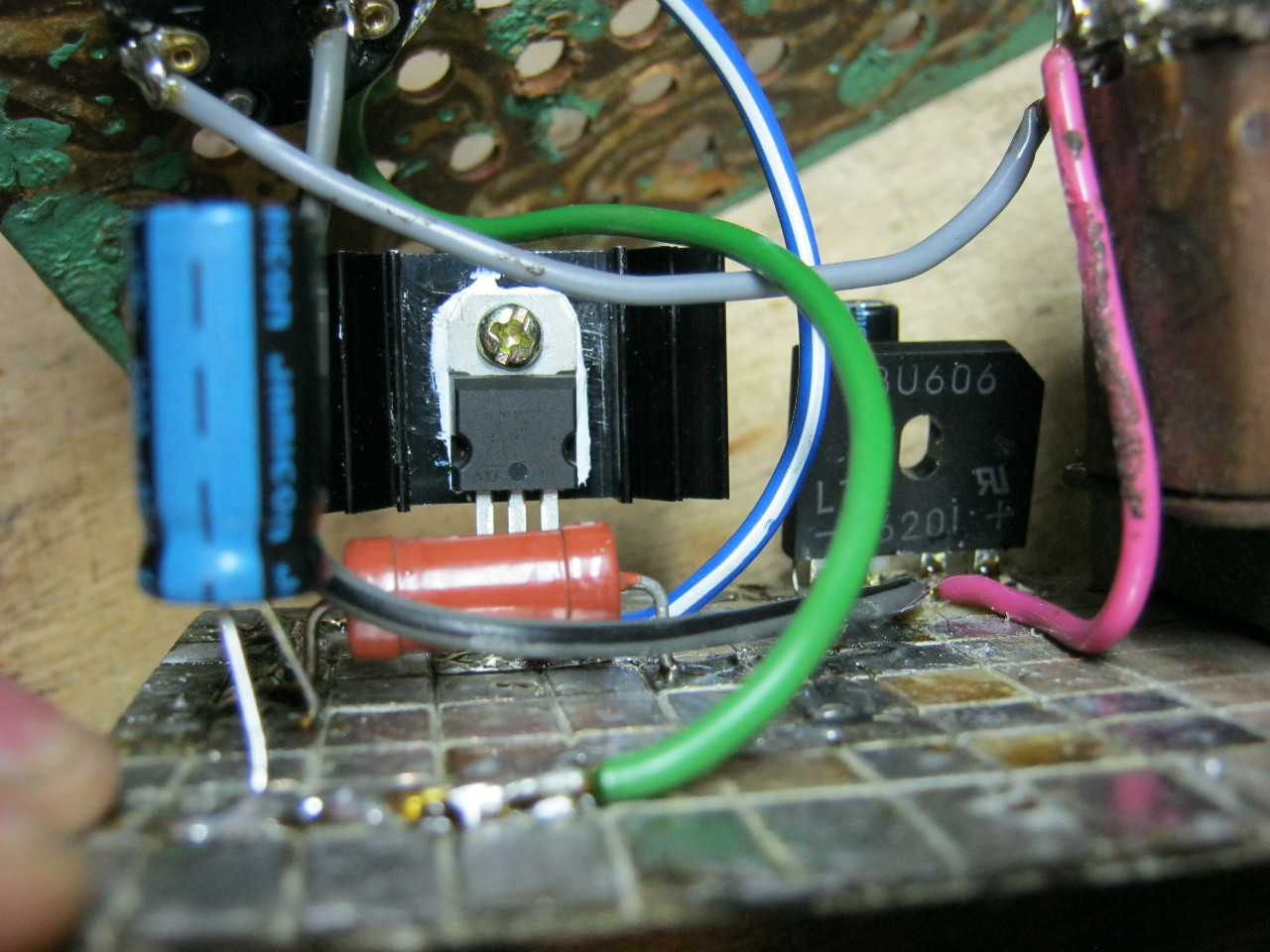
Take a close look at the LM317T in the circuit itself! The third leg (3) of the microcircuit is connected to capacitor C1, that is, the third leg is INPUT, and the second leg (2) is connected to capacitor C2 and a 200 Ohm resistor and is an OUTPUT.
Using a transformer, from a mains voltage of 220 Volts we get 25 Volts, no more. Less is possible, no more. Then we straighten the whole thing with a diode bridge and smooth out the ripples using capacitor C1. All this is described in detail in the article on how to obtain constant voltage from alternating voltage. And here is our most important trump card in the power supply - this is a highly stable voltage regulator chip LM317T. At the time of writing, the price of this chip was around 14 rubles. Even cheaper than a loaf of white bread.
LM317T is a voltage regulator. If the transformer produces up to 27-28 volts on the secondary winding, then we can easily regulate the voltage from 1.2 to 37 volts, but I would not raise the bar to more than 25 volts at the transformer output.
The microcircuit can be executed in the TO-220 package:

or in D2 Pack housing

It can pass a maximum current of 1.5 Amps, which is enough to power your electronic gadgets without voltage drop. That is, we can output a voltage of 36 Volts with a current load of up to 1.5 Amps, and at the same time our microcircuit will still output 36 Volts - this, of course, is ideal. In reality, fractions of volts will drop, which is not very critical. With a large current in the load, it is more advisable to install this microcircuit on a radiator.
In order to assemble the circuit, we also need a variable resistor of 6.8 Kilo-Ohms, or even 10 Kilo-Ohms, as well as a constant resistor of 200 Ohms, preferably from 1 Watt. Well, we put a 100 µF capacitor at the output. Absolutely simple scheme!
Previously, I had a very bad power supply with transistors. I thought, why not remake it? Here is the result ;-)

Here we see the imported GBU606 diode bridge. It is designed for a current of up to 6 Amps, which is more than enough for our power supply, since it will deliver a maximum of 1.5 Amps to the load. I installed the LM on the radiator using KPT-8 paste to improve heat transfer. Well, everything else, I think, is familiar to you.
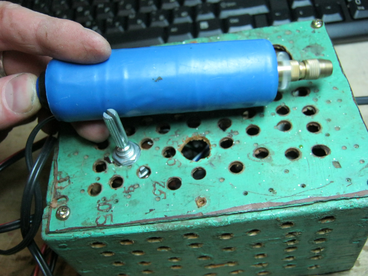
And here is an antediluvian transformer that gives me a voltage of 12 volts on the secondary winding.

We carefully pack all this into the case and remove the wires.

So what do you think? ;-)

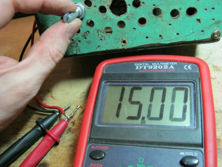
The minimum voltage I got was 1.25 Volts, and the maximum was 15 Volts.

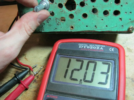
I set any voltage, in this case the most common are 12 Volts and 5 Volts

Everything works great!
This power supply is very convenient for adjusting the speed of a mini drill, which is used for drilling circuit boards.
By the way, on Ali you can immediately find a ready-made set of this block without a transformer.

Too lazy to collect? You can buy a ready-made 5 Amp for less than $2:

You can view it at this link.
If 5 Amps is not enough, then you can look at 8 Amps. It will be enough for even the most seasoned electronics engineer:

Greetings, friends. Today I made a small selection of materials for assembling an adjustable power supply. LT1083CP is used as a regulating element; voltage regulation limits range from 1.5 to 30V, current up to 7 Amperes. This scheme can be found in the form of construction kits (KIT) on Aliexpress, and so on some selling sites. The set looks like this:

View of the board from both sides:

Based on a photograph of a printed circuit board taken from Ali, I made a copy in LAY6 format for making it myself, but first, I’ll give a schematic diagram:

I would like to immediately draw your attention to how the LED is connected in the diagram. As I understand it, it serves as an indicator that the power supply is on. If we have an adjustable voltage value at the output, and the regulator of this value is turned to the minimum value, the LED simply will not light up, therefore I consider it advisable to connect the LED + R3 chain to the input of the U1 stabilizer, where the voltage is more or less constant, not counting the possible drawdown when high currents. This is the LED connection option implemented in the watering can, which looks like this:
There is nothing special to explain in the diagram, the standard connection of a linear stabilizer, the only thing I would like to draw attention to is the self-resetting fuse that comes in the KIT kit, marked FU on the board. If you decide to make an external fuse, you can wire it out by connecting it to the same place, but for those who decide to make an exact copy, I will give the appearance of such an element:

You can easily buy it on Ali for 100 rubles per ten with free delivery. See the rest of the list of elements below, there are not many of them, so the list will be single:
LT1083CP – 1 pc.
R1 – 100R/2W – 1 pc.
R2 – variable resistor 5k (multi-turn in the kit, you can bring a regular one to the front panel of the case)
R3 – 5k6/0.25W – 1 pc.
C1, C5 – 105 = 1mF/50...63V NON-POLAR – 1 pc.
C2 – 4700mF/50V – 1 pc. (You can put 6800mF or 10000mF/50V if it fits in size)
C3 – 10mF/50V – 1 pc.
C6 – 1000mF/50V – 1 pc. (470mF/50V is set on the KIT board)
D1, D4, D6, D7 – 10A10 (10A diodes) – 1 pc.
D2, D3 - 1N4007 – 2 pcs.
LED1 – red LED 3mm - 1 pc.
Connector 2Pin (Connector Terminal block 2 pins) - 2 pcs.
Transformer - secondary winding 24V 8A (not included in the set)
For those who find it more convenient to place a control potentiometer on the board, the watering can looks like this:
Well, the last thing I wanted to add is a way to connect two identical boards to implement a bipolar source:

The archive contains sources and datasheets for 10-amp 10A10 diodes and the LT1083 linear stabilizer.
The size of the archive with materials for assembling an adjustable power supply on the LT1083 is 1.3 Mb.
Buying this power supply as a set is cheaper (330 rubles), and you don’t need to make the board yourself, link to Ali - LT1083 KIT
Voltage regulator LM338, manufactured by Texas Instruments, is a general-purpose integrated circuit that can be connected in numerous ways to produce high-quality power circuits.
The LM338 integrated circuit is available in two housing options: a metal TO-3 housing and a plastic TO-220 housing:


The calculation of the parameters of the LM338 stabilizer is identical to the calculation of the LM317. The online calculator is located.
The following examples will show you some very interesting and useful power circuits built using the LM338.
This diagram is a typical LM338 harness connection. The power supply circuit provides an adjustable output voltage from 1.25 to the maximum supplied input voltage, which should not exceed 35 volts.

Variable resistor R1 is used to smoothly regulate the output voltage.
This circuit produces an output voltage that can be equal to the input voltage, but the current varies well and cannot exceed 5 amperes. Resistor R1 is precisely selected to maintain a safe 5 amp limiting current limit that can be drawn from the circuit.

As mentioned earlier, the LM338 microcircuit alone can handle only 5A maximum, however, if it is necessary to obtain a higher output current, in the region of 15 amperes, then the connection diagram can be modified as follows:

In this case, three LM338 are used to provide high current load with the ability to regulate the output voltage.
Variable resistor R8 is designed for smooth adjustment of the output voltage
In the previous power supply circuit, a variable resistor was used to regulate the voltage. The circuit below allows you to obtain the required output voltage levels using a digital signal supplied to the bases of the transistors.

The value of each resistance in the transistor collector circuit is selected in accordance with the required output voltage.
In addition to power supply, the LM338 IC can also be used as a light controller. The circuit shows a very simple design where a phototransistor replaces a resistor, which is used as a component to regulate the output voltage.

The lamp, the illumination of which must be kept at a stable level, is powered by the output of LM338. Its light falls on the phototransistor. When the illumination increases, the resistance of the photoresistor drops and the output voltage decreases, and this in turn reduces the brightness of the lamp, maintaining it at a stable level.
The following circuit can be used to charge 12 volt lead acid batteries. The RS resistor can be used to set the required charging current for a specific battery.

By selecting resistance R2, you can adjust the required output voltage in accordance with the type of battery.
Some sensitive electronic circuits require soft power switching. Adding capacitor C2 to the circuit makes it possible to smoothly increase the output voltage to the set maximum level.

The LM338 can also be configured to maintain the heater temperature at a certain level.

Here another important element has been added to the circuit - the LM334 temperature sensor. It is used as a sensor which is connected between adj LM338 and ground. If the heat from the source increases above a predetermined threshold, the resistance of the sensor decreases and the output voltage of the LM338 decreases accordingly, subsequently reducing the voltage across the heating element.
(729.7 Kb, downloads: 5,150)
The master whose device was described in the first part, having set out to make a power supply with regulation, did not complicate things for himself and simply used boards that were lying idle. The second option involves the use of an even more common material - an adjustment has been added to the usual block, perhaps this is a very promising solution in terms of simplicity, given that the necessary characteristics will not be lost and even the most experienced radio amateur can implement the idea with his own hands. As a bonus, there are two more options for very simple schemes with all the detailed explanations for beginners. So, there are 4 ways for you to choose from.
We'll tell you how to make an adjustable power supply from an unnecessary computer board. The master took the computer board and cut out the block that powers the RAM.
This is what he looks like.
Let's decide which parts need to be taken and which ones not, in order to cut off what is needed so that the board has all the components of the power supply. Typically, a pulse unit for supplying current to a computer consists of a microcircuit, a PWM controller, key transistors, an output inductor and an output capacitor, and an input capacitor. For some reason, the board also has an input choke. He left him too. Key transistors - maybe two, three. There is a seat for 3 transistors, but it is not used in the circuit.
The PWM controller chip itself may look like this. Here she is under a magnifying glass.

It may look like a square with small pins on all sides. This is a typical PWM controller on a laptop board.

This is what a switching power supply looks like on a video card.

The power supply for the processor looks exactly the same. We see a PWM controller and several processor power channels. 3 transistors in this case. Choke and capacitor. This is one channel.
Three transistors, a choke, a capacitor - the second channel. Channel 3. And two more channels for other purposes.
You know what a PWM controller looks like, look at its markings under a magnifying glass, look for a datasheet on the Internet, download the pdf file and look at the diagram so as not to confuse anything.
In the diagram we see a PWM controller, but the pins are marked and numbered along the edges.

Transistors are designated. This is the throttle. This is an output capacitor and an input capacitor. The input voltage ranges from 1.5 to 19 volts, but the supply voltage to the PWM controller should be from 5 volts to 12 volts. That is, it may turn out that a separate power source is required to power the PWM controller. All the wiring, resistors and capacitors, don’t be alarmed. You don't need to know this. Everything is on the board; you do not assemble a PWM controller, but use a ready-made one. You only need to know 2 resistors - they set the output voltage.
Resistor divider. Its whole point is to reduce the signal from the output to about 1 volt and apply feedback to the input of the PWM controller. In short, by changing the value of the resistors, we can regulate the output voltage. In the case shown, instead of a feedback resistor, the master installed a 10 kilo-ohm tuning resistor. This was sufficient to regulate the output voltage from 1 volt to approximately 12 volts. Unfortunately, this is not possible on all PWM controllers. For example, on PWM controllers of processors and video cards, in order to be able to adjust the voltage, the possibility of overclocking, the output voltage is supplied by software via a multi-channel bus. The only way to change the output voltage of such a PWM controller is by using jumpers.

So, knowing what a PWM controller looks like and the elements that are needed, we can already cut out the power supply. But this must be done carefully, since there are tracks around the PWM controller that may be needed. For example, you can see that the track goes from the base of the transistor to the PWM controller. It was difficult to save it; I had to carefully cut out the board.
Using the tester in dial mode and focusing on the diagram, I soldered the wires. Also using the tester, I found pin 6 of the PWM controller and the feedback resistors rang from it. The resistor was located in the rfb, it was removed and instead of it, a 10 kilo-ohm tuning resistor was soldered from the output to regulate the output voltage; I also found out by calling that the power supply of the PWM controller is directly connected to the input power line. This means that you cannot supply more than 12 volts to the input, so as not to burn out the PWM controller.
I soldered the input voltage plug, voltage indicator and output wires. We connect an external 12 volt power supply. The indicator lights up. It was already set to 9.2 volts. Let's try to adjust the power supply with a screwdriver.


The master had already made similar power supplies before. One is cut out with your own hands from a laptop board.

This is the so-called standby voltage. Two sources of 3.3 volts and 5 volts. I made a case for it on a 3D printer. You can also look at the article where I made a similar adjustable power supply, also cut from a laptop board (https://electro-repair.livejournal.com/3645.html). This is also a PWM power controller for RAM.
We will talk about the power supply for a Canon inkjet printer. Many people have them idle. This is essentially a separate device, held in the printer by a latch.
Its characteristics: 24 volts, 0.7 amperes.

I needed a power supply for a homemade drill. It's just right in terms of power. But there is one caveat - if you connect it like this, the output will only get 7 volts. Triple output, connector and we get only 7 volts. How to get 24 volts?
How to get 24 volts without disassembling the unit?
Well, the simplest one is to close the plus with the middle output and we get 24 volts.
Let's try to do it. We connect the power supply to the 220 network. We take the device and try to measure it. Let's connect and see 7 volts at the output.
Its central connector is not used. If we take it and connect it to two at the same time, the voltage is 24 volts. This is the easiest way to ensure that this power supply produces 24 volts without disassembling it.
A homemade regulator is needed so that the voltage can be adjusted within certain limits. From 10 volts to maximum. It's easy to do. What is needed for this? First, open the power supply itself. It is usually glued. How to open it without damaging the case. There is no need to pick or pry anything. We take a piece of wood that is heavier or have a rubber mallet. Place it on a hard surface and tap along the seam. The glue comes off. Then they tapped thoroughly on all sides. Miraculously, the glue comes off and everything opens up. Inside we see the power supply.

We'll get the payment. Such power supplies can be easily converted to the desired voltage and can also be made adjustable. On the reverse side, if we turn it over, there is an adjustable zener diode tl431. On the other hand, we will see the middle contact goes to the base of transistor q51.


If we apply voltage, then this transistor opens and 2.5 volts appears at the resistive divider, which is needed for the zener diode to operate. And 24 volts appears at the output. This is the simplest option. Another way to start it is to throw away transistor q51 and put a jumper instead of resistor r 57 and that’s it. When we turn it on, the output is always 24 volts continuously.
You can change the voltage, make it 12 volts. But in particular, the master does not need this. You need to make it adjustable. How to do it? We throw away this transistor and replace the 57 by 38 kilo-ohm resistor with an adjustable one. There is an old Soviet one with 3.3 kilo-ohms. You can put from 4.7 to 10, which is what it is. Only the minimum voltage to which it can lower it depends on this resistor. 3.3 is very low and not necessary. The engines are planned to be supplied at 24 volts. And just from 10 volts to 24 is normal. If you need a different voltage, you can use a high-resistance tuning resistor.
Let's get started, let's solder. Take a soldering iron and hair dryer. I removed the transistor and resistor.

We soldered the variable resistor and will try to turn it on. We applied 220 volts, we see 7 volts on our device and begin to rotate the variable resistor. The voltage has risen to 24 volts and we rotate it smoothly and smoothly, it drops - 17-15-14, that is, it decreases to 7 volts. In particular, it is installed on 3.3 rooms. And our rework turned out to be quite successful. That is, for purposes from 7 to 24 volts, voltage regulation is quite acceptable.

This option worked out. I installed a variable resistor. The handle turns out to be an adjustable power supply - quite convenient.
Video of the channel “Technician”.
Such power supplies are easy to find in China. I came across an interesting store that sells used power supplies from various printers, laptops and netbooks. They disassemble and sell the boards themselves, fully functional for different voltages and currents. The biggest plus is that they disassemble branded equipment and all power supplies are of high quality, with good parts, all have filters.
The photos are of different power supplies, they cost pennies, practically a freebie.
A simple version of a homemade device for powering devices with regulation. The scheme is popular, it is widespread on the Internet and has shown its effectiveness. But there are also limitations, which are shown in the video along with all the instructions for making a regulated power supply.


What is the simplest regulated power supply you can make yourself? This can be done on the lm317 chip. It almost represents a power supply itself. It can be used to make both a voltage- and flow-regulated power supply. This video tutorial shows a device with voltage regulation. The master found a simple scheme. Input voltage maximum 40 volts. Output from 1.2 to 37 volts. Maximum output current 1.5 amperes. 
Without a heat sink, without a radiator, the maximum power can be only 1 watt. And with a radiator 10 watts. List of radio components. 


Let's connect an electronic load to the output of the device. Let's see how well it holds current. We set it to minimum. 7.7 volts, 30 milliamps.
 Everything is regulated. Let's set it to 3 volts and add current. We’ll only set larger restrictions on the power supply. We move the toggle switch to the upper position. Now it's 0.5 ampere. The microcircuit began to warm up. There is nothing to do without a heat sink. I found some kind of plate, not for long, but enough. Let's try again. There is a drawdown. But the block works. Voltage adjustment is in progress. We can insert a test into this scheme.
Radioblogful video. Soldering video blog.


