Combine the beloved timbre color, natural sound and overload resistance of tube amplifiers with the reliability, durability and fidelity of RF transistor designs. The idea is far from new. Today we will talk about modern hybrid Hi-Fi amplifiers.
At the dawn of the formation of the AuDDiolab section, I talked about this interesting class of devices. It's time to give it the attention it deserves. What exactly is the struggle for when creating a hybrid amplifier? After all, a “purebred” class A tube unit is fully capable of playing music more than well. Yes, that's true.
Richter Sorcerer - this is what the dream of many audiophiles looks like
But even class A has an Achilles heel. The same fatal flaw that limits its widespread distribution. And this is an exponential increase in the complexity of the design and cost of such an amplifier when trying to bring its power to any serious indicators. The point here is that without simply sky-high requirements for the quality of the element base and installation, and even for the power supply of the device, it is simply impossible to achieve a nonlinear distortion coefficient (THD) that fits within the Hi-Fi framework. Therefore, the lot of single-ended class A tubes remains low-power solutions that produce amazingly high-quality sound.

Incredibly, a THD of 1.2% is considered good for high-power tube amplifiers.
This is where the need arises for an alternative solution that can provide comparable sound levels and high power levels at the same time. And at the same time be economically feasible. Thus began the need for powerful hybrid amplifiers.

Hybrid monster Magnat RV 3. 2 x 200 Watt and THD 1%. Indicators unattainable for a simple “lamp”
But the market does not live by power alone! There is also another extreme - headphone amplifiers. Where, in addition to the power sufficient to drive high-impedance headphones, the requirements for the SOI level reach a completely different level. By default, Hi-Fi headphones are a much more precise instrument than acoustics. And they will definitely “voice out” all the sins behind the amplifier. Directly into the listener's ear canals. Therefore, it would be great to curb the “tough temper” of the lamps, reducing distortion to a minimum, and make the design as cheap as possible. This is how hybrid headphone amplifiers appeared. Often simple, relatively cheap transformerless solutions. But many models are really capable of producing sound at such a level that their “purebred” tube counterparts have to blush profusely.

Apex Peak/Volcano will make your headphones sing
Of course, the list of varieties of “hybrids” does not end there. Any modern “tube” microsystem for players and smartphones is in practice equipped with a hybrid amplifier. Samsung, Roth, Fatman. The list goes on and on. Just remember that Kickstarter.
One thing is absolutely clear - in the foreseeable future, “classic” lamp solutions will only have a place in the ultimate Hi-End segment. And the near-budget and mid-price pieces of the lamp pie will entirely go to hybrid designs.

Stereo Hybrid Tube Amp. $149. No comments
So what is their secret? The answer is simple - in transistor control of lamp operating modes. In fact, a small number of transistor elements with minimal wiring can replace long, expensive and at the same time increasing the SOI level “garlands” of capacitors, resistors and other elements designed to keep the tube standards within the limits of decency using old-fashioned methods. On the one hand, we get an increase in sound reliability, and on the other hand, simplification (and therefore reduction in cost) of the design.

Simplicity is the key to great sound
Yes, many venerable audiophile “gurus” still do not take such decisions seriously because they allegedly contain feedback that has a detrimental effect on the sound. In practice, transistor elements in such circuits do not act as signal amplifying elements. Therefore, such concerns should not be taken seriously.
That's all for today. I strongly recommend that all readers of the AuDDiolab column become familiar with the sound of “hybrids” if possible. This may well be exactly what many of you were looking for. And also write in the comments if you would be interested in a series of materials about building a hybrid amplifier on your own. If I understand that a “critical mass” of responses has been reached, such a project will not take long to come. See you later! :)
If you find an error, please highlight a piece of text and click Ctrl+Enter.
At numerous requests from radio amateurs, I present an improved and more complete diagram of a hybrid ULF with a detailed description, a list of parts and a power supply diagram. The lamp at the input of the 6N6P hybrid ULF circuit was replaced with a 6N2P. You can also install the 6N23P, which is more common in old lamps, in this unit. Field-effect transistors are replaceable with other similar ones - with an insulated gate and a drain current of 5A and higher. Variable R1 - 50 kOhm is a high-quality variable resistor for the volume control. You can set it up to 300 kOhm, nothing will worsen. Be sure to check the regulator for the absence of rustles and unpleasant friction during rotation. Ideally, you should use ALPS RG - this is a Japanese company producing high-quality regulators. Don't forget about the balance regulator.Trimmer resistor R5 - 33 kOhm inserts voltage zero on the speaker in ULF silent mode. In other words, by applying power to the transistors and instead of a speaker (!), connecting a powerful 4-8 Ohm 15 watt resistor, we achieve zero voltage on it. We measure with a sensitive voltmeter, since it should be absolute zero. The diagram of one hybrid ULF channel is shown below.

The remaining resistors are 0.125 or 0.25 watts. In short, any small ones. A 10,000 µF capacitor can be safely reduced to 100 µF, but it is drawn according to the old designation. We set all capacitors for anad supply to 350V. If it’s difficult to get 6.8 μF, set it to at least 1 μF (that’s what I did). We will replace the quiescent current control transistor with KT815 or KT817. This will not affect the sound, it simply corrects the current there. Naturally, we need another copy of the hybrid ULF for the second channel.
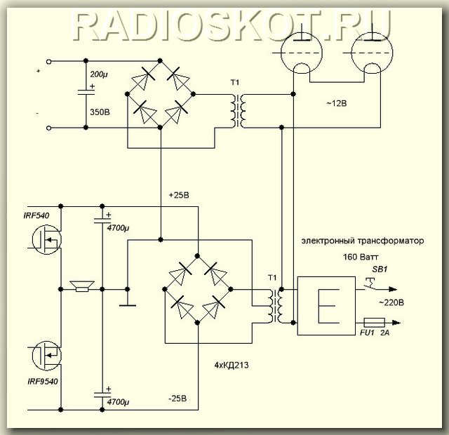
To power the transistors, you need a bipolar source of +-20 (35) V with a current of 4A. You can use a regular transformer. Since more power was not required, I installed a 60-watt trans from a VCR with a corresponding reduction in output power. Filtration is simple - a diode bridge and a capacitor. With a quiescent current of 0.5A, a capacity of 10,000 microfarads per channel is sufficient. Capacitors C3, C4, C5 160V each, no less. Or more just in case. R8 is a small tuning resistor - turned with a screwdriver. It sets the quiescent current of the output transistors (in the absence of a signal). You need to set the current from 0.3A - mode AB to 2A - mode A. In the second case, the sound quality is much better, but it will not heat up much. It can be used for power supply with an additional ring and 12-turn windings - it receives 12V from the transformer, and two 20V each - this is the secondary. In this case, the bridge diodes must be high-frequency; simple KD202 will burn out instantly.

We feed the filament with 12 volts by connecting the filaments of both lamps in series. I took the anode voltage of 300V using a small transformer (5 watts) from a Chinese multi-voltage adapter. You can't power anything from that parody except an LED, but in this hybrid it comes in handy. We supply 12V to its 15-volt secondary from an electronic (or conventional) transformer, and remove the voltage from the 220-volt network. The current is certainly not that great, but both 6N2P lamps pull only 5mA across the anode, so they don’t need more.
Discuss the article HYBRID ULF
Hybrid amplifiers, or tube amplifiers without an output transformer
Many beginning amateur audiophiles are deterred from building a good tube amplifier by the complexity of making an output transformer. You need to find somewhere a good powerful magnetic circuit (core) from OSM or TS-180...250, kilometers of wire. And seasoned audiophiles say that the already multi-turn primary winding, which you are tormented to wind, must also be sectioned, separating it with pieces of the secondary. Which way should I put it all in, how can I avoid getting confused when connecting?..
Meanwhile, there is an approach, perhaps very controversial, which consists of replacing the output transformer (and the output lamp, for that matter) with... a transistor. Yes, yes, that same hated “stone” silicon, from which people are so eager to move away to a transparent vacuum.
Using a transistor as a current amplifier can significantly simplify the output part of the amplifier, but is it worth it? After all, here we lose a significant amount of tube power - an entire output tube and transformer. How much will this take away from the sound and how much will silicon add?
Until you collect it, you won’t know. Perhaps someone will like this compromise between lamp-likeness and simplicity. Therefore, here we present two schemes that have been repeated by a large number of people. Some people immediately liked the sound of such amplifiers, while others were puzzled and forced to listen for a long time.
First scheme of an 8W hybrid amplifier authored by Vladislav Kreimer was published in one of the issues of the Radio Amateur magazine. According to the author, the overall sound character is formed by the 6N23P triode, and the emitter follower on the KT825 composite transistor only amplifies the current, “matching” the high resistance of the lamp with the low resistance of the acoustics. The output stage operates in hard "A" mode with a quiescent current of 1.25 amperes, which is dissipated by resistor R3 - 27 watts of heat, however. The voltage drop across resistor R2 provides a small amount of feedback. The author notes the excellent sound qualities of such a hybrid. SOI - less than 1%.

Amplifier sensitivity - 0.6V. The linear frequency response in the lower part is determined by the capacitance of capacitor C1; with the nominal value indicated on the diagram, it is about 5 Hz.
Resistor R3 is a wire-wound resistor with a power of 20W. As already noted, it gets very hot. R2 - two-watt, can be made up of two parallel-connected one-watt ones. By changing its resistance within 0.2-1.2 Ohms, you can change the amount of feedback. With less resistance, the sensitivity will be greater, and the sound will be more “warm” and “fat,” as the author described it. As you increase the sensitivity, the sensitivity will decrease and the sound will become more transparent. The lamp must be selected so that the transistor emitter has a voltage of 10-12.5 V. About the transistor itself: here you can use KT825 with any letter index. The author notes that old transistors produced during the USSR “sound” better. Perhaps imported analogues will be even better. You can also use two ordinary transistors instead of a composite one; it is especially tempting to do this with germanium. Requires the use of a 1000 sq. cm radiator. The transistor and R3 will produce a total of about 30W.
The amplifier's power supply must be of high quality, without ripple. The diagram shows one of the options. The choke must have at least 300 turns with a diameter of 0.3-0.5 mm on the magnetic core from a 10-20 W transformer. Winding resistance - 1...2 Ohm. The power supply should provide a voltage of about 22 volts at the top terminal of R3. Don't forget about the lamp's filament power supply, it's not shown in the diagram.
If the amplifier will self-excite at HF, anti-ringing chokes of 15 turns on small ferrite rings can be added to the lamp grids.
Those who like to experiment with the “fatness” of the sound can bypass R2 with a capacitor with a capacity of 4700 μF, which will eliminate feedback. This will significantly increase the amplifier's sensitivity and slightly reduce power.
The resistance of resistor R3 must be equal to the load resistance.
Second scheme by V. Grishin with SOI 0.3% at rated power (16-20W). Unlike the previous circuit, here the lamp operates in linear mode. The bipolar transistor is replaced by a field-effect transistor, the bias of which is formed by the chain R5, R5, R6, D1, C2 to set the required quiescent current (3A) in class “A”. The high capacitance of C2 ensures a soft transition of the transistor to operating mode when turned on.
The transistor mode and ratings in the diagram are calculated for a load with a resistance of 4 Ohms. For 8 Ohms, the supply voltage of the output stage should be increased to 20 V, the quiescent current should be set to 2.1A, and the inductance of the inductor should be doubled.
This unusual designation of the throttle is no coincidence. In the author's version, its magnetic core is combined from ferrite and iron. The winding resistance is very small, so the transistor current is “constantly” shorted to ground. The variable component is supplied to the acoustics. A description of how to make a throttle can be found in Radio No. 3, 2013.
As in the first scheme, it is very important to ensure good nutrition. The capacitances in the filters of the output stage power supply can reach up to 47000 μF (to power two channels). In the anode supply, the author used a kenotron rectifier, which gives a smooth increase in voltage. When using a diode rectifier, the transistor gate should be protected with a zener diode.
The lamp can be replaced with 6S2P, 6N1P, recalculating the values of resistors R2 and R3 for the desired linear section of the characteristic. The zener diode can be replaced with KS175Zh, KS210Zh. The field-effect transistor can be replaced with a similar one in parameters (for example, IRF830, IRFZ24N), but the author considers it irreplaceable in terms of sound quality. Transformer for powering the output stage - with a threefold power reserve, 150...250 W. With 4-ohm acoustics, the voltage of the secondary winding of this transformer should be 12 V, for 8-ohm - 18 V. Anode transformer - no more than 15 W. You can try to select a step-down transformer by connecting it “in reverse” to the secondary winding of the output stage power transformer.
The choke can be made on an armored magnetic circuit ShLM 20x40. For 4 Ohm speakers you should use a wire with a diameter of 2 mm, for 8 Ohms - 1.78 mm. Those who want to get rid of winding products can recommend ideas from the so-called. followers: scheme. There is also a diagram with a current generator in Radio No. 12, 2012.
This hybrid amplifier is configured by setting the required quiescent current, monitoring it during a 3-4 hour warm-up period.
The input voltage should be no more than 2 volts. The power of the acoustics used should be doubled. It is important that two-way acoustics are preferable for this amplifier, because If there is a mid-frequency filter in the acoustics, the advantage of directly connecting the load to the output stage is lost.
The LM series amplifier chips have the best sound among analogues. This also applies to flagship models of various levels, such as LM1875, LM3876 and its logical continuation - LM3886. The author's article continues the debate on the topic of circuit design and Thorsten's developments. An amplifier based on LM3875 is being considered. Its best sound, stability and linearity is achieved with inverting switching. However, this connection, when operating on the classic output impedance of the source, has a number of disadvantages. In short: with increasing frequency, the nonlinearity of the frequency response and phase increases. This is due to the fact that with an inverting connection, the signal must come from a current source, and CD players and sound cards have an output impedance of about 200 Ohms. The current source on field-effect transistors is also eliminated due to high losses, high input capacitance and pronounced nonlinearity. A current buffer on a triode successfully copes with this task.
In addition, this kind of buffer has a voltage gain of less than 1. Due to this, the OOS depth of the microcircuit itself is reduced, which also has an extremely beneficial effect on the sound quality. It is known that deep OOS, implemented by a classical divider, coarsens and deadens the sound. In the scheme proposed by Rasmussen ( Fig.1), a T-shaped OOS has been introduced, which increases the input resistance at the inverting input and makes it possible to reduce the grounding resistance at the direct input. The downside of this approach is the increase in noise and interference, but this is the first impression. If the wiring and shielding of the amplifier unit are done properly, interference will be almost invisible.
Now let’s look at what I personally didn’t like about the original scheme.
The author has LM3875 installed as a PA. Its disadvantages are imperfect protection, operation only with an 8-Ohm load, and low power. Instead, the LM3886 MC with a full set of protections and a powerful output stage was chosen, allowing it to deliver long-term power of 68 W and short-term power of 135 W into a 4-Ohm load. In addition, the amplifier is equipped with a full set of protections and a built-in mute mode.
At the exit Fig.1 There is a current limiter - a wirewound SQP resistor. The SPiKe system implemented in the LM3886 allows you to abandon it.
For the convenience of mixing channel parameters and reducing the size of the amplifier, the popular vacuum double triode 6N23P-EV was used as a buffer. It is distinguished by a low supply voltage, which is relevant in this circuit, and at the same time, good sound. Although we have to admit that in this case its application is far from classical.
For our own reasons, the following features were added to the board:
Taking into account all the above considerations, the scheme took the following form ( Fig.2):
Here are the elements C 1 , C 3 , C 4 as well as terminals CN 1.. CN 6 – common for both channels. Each channel also contains half of a double triode 6N23P-EV .
Here, let’s take a break from the circuit design of the PA for a few seconds and consider the power supply, so as not to return to this topic again.
To power the entire circuit, a four-polar power supply with a common ground and an independent heating winding is used, the circuit of which is shown in Fig.3:
Diode bridges are either ready-made or assembled from diodes of the types that appeal to you, everything from D213 to Schottky diodes. For ±36 V 0.2 A – D 1 for a voltage of at least 200 V and a current of at least 4 A. For ±27V 4 A – D 2 for a voltage of at least 100 V and a current of at least 8 A. For incandescent - D 3 for any voltage and current of at least 4 A. This seemingly overestimation of parameters is not accidental. The fact is that, despite the peak reserve of the diodes, the current during charging of the containers exceeds the nominal one several times. But the price of diodes or ready-made bridges does not differ much, so for your own peace of mind I do not advise saving.
Capacities C 1, C 2 (for voltage not less than 50 V), C 5, C 6 (for voltage not less than 35 V), C 9 (for a voltage of at least 16 V) – imported electrolytic type K50-35. C 3, C 4, C 7, C 8, C 10 – type K73-17 at 63 V.
Any power transformer with an overall power of at least 200 W that satisfies the parameters of currents and voltages in the secondary windings indicated in the diagram (incandescent current of at least 0.8 A per lamp) can be used as a transformer.
In addition, it is possible to use two separate transformers. One is powerful for powering the PA, and the other is for powering the lamp. The second can be selected from a number of standardized lamp " T transformers A butno- N Akalnye". I use TAN1.
So, we managed to fit both channels onto one printed circuit board measuring 130x80 mm. Assembled module (without additional blocking containers) C8, C9 ) looked like this ( Fig.4).
Cute, isn't it?
The original layout of the elements is shown in Fig.5:
Now a few words about the details and the intricacies of assembly.
Most resistors require pairing across channels with an accuracy of at least 1%. These conditions are fully satisfied by resistors of the C2-23 series. So, selection is required R 1 , R 3.. R 9 . Moreover R 1 , R 3 And R 4 It is better to use metal film type MLT, OMLT or imported analogues.
Resistors R 2 And R 10 no selection required. Can be of the MLT-0.25, S1-4 or S2-23 type at 0.125/0.25 W. R 11 And R 12 – imported at 2 W. The output inductance winds over R 11 , dressed in an insulating cambric, with a wire in enamel or epoxy insulation with a diameter of 0.6-0.8 mm until filled and soldered to the legs of the resistor. Although in this case I am a resistor R 11 didn't install. Instead, a coil was soldered, wound on the handle of a file and containing 15 turns of wire with a diameter of 0.8 mm.
VR 1 , VR2 – double variable resistor. In my case, Taiwan for 44 clicks, selected with an accuracy of 0.5% from 5 pieces.
C 1 , C 3 , C 8 , C 9 , C 10 – polar electrolytic type K50-35, preferably imported well-known brands. However, the circuit does not contain electrolytes in the audio circuit, which significantly improves the sound, reduces the criticality of the elemental base and increases the reliability of the system as a whole.
C1 – 16 V, C3 – 100 V, S8-S10 – 50 V.
C 4 , C 5 , C 7 , C 11 – metal film type K73-17. C 4 - at 250 V, the rest - at 63 V.
C2 – metal film or metal paper of the highest available quality, preferably no worse than polypropylene. The permissible voltage is also not lower than 63 V. Although this circuit sounds great with a K73-17 capacitor.
C6 – ceramics, preferably without piezo effect. KM or disk type. In extreme cases, of course, the K10-17B will do, but it’s hard to imagine a worse option.
Active components
The LM3886 amplification IC can be replaced with similar pinouts, taking into account the features of each. Purely theoretically, the circuit works with any MS built on the principle of a powerful op-amp. Attention! On the MC body there is a minus power supply!
Lamp R.O. 1 6N23P-EV is changed to 6N23P or an imported analogue ECC88. It is installed in a ceramic or any other socket designed for mounting on a printed circuit board or on a UMZCH chassis and is connected to the board with copper conductors.
In addition, taking into account modern trends in design, separate amplifier blocks have been developed for L.M. 3886 , which are installed on the radiator inside the UMZCH housing, and the lamp is installed in a special socket located on the housing cover. In this version, the entire llama harness ( R 1 , R 2 , 2x R 3 , C 3 , C 4 ) is carried out by mounted mounting directly on the socket terminals. And then it is connected to the power amplification units using a shielded signal cable. Don't forget to ground the lamp shield.
The printed circuit board of one PA channel is given on Figure 6:
Since it takes about 5 s to warm up the lamp, all these 5 s the amplifier input “hangs in the air”. At this time, all imaginable interference and a very noticeable rumble are present at the output. This can be avoided in two ways - by using a mute circuit or a relay to delay the turn-on. In both cases, the control signal will be a bipolar transistor with an RC divider in the base. If the delay is not enough, simply increase the value R 1 .
A diagram of such a delay is given in Figure 7:
In addition, at the time of modeling I had relays lying around TR 81 companies TTI . A printed circuit board was laid out for them. Its drawing can also be used as a guide for wiring for any relay you like with a normally open contact group. The board layout is given on Fig.8.
Details:
VR 1 – to the supply voltage of the relay winding. You can take it a little higher (about 2 V - drop across the transistor). In my case 12 V, i.e. stabilizer 7812..7815 .
C2 – on the voltage of the PA supply arm.
C1 – higher than stabilization voltage VR 1
This protection is connected to the positive side of the PA power supply (powerful transformer). The negative power terminal and the mute circuits of both amplifier channels (or all, if there are more channels) connected together are connected to the relay.
So finally SOUND
Fans of “tube sound” will really like this amplifier. What immediately catches your eye is the excellent vocals, the stage design and its incredible depth for transistor amplifiers. Unlike the typical sound of the LM3886, the HF is not washed out in this inclusion. They sound very subtle and precise. Silver and crystal do not smudge, as in a non-inverting inclusion. It is also impossible not to note the presence of a dense, collected and powerful, but extremely well-developed bass, which has always been so difficult to achieve from LM. Jazz and Blues sound so soulful that when listening, I often found myself getting goosebumps running down my spine.
The sound of this amplifier cannot be called absolutely accurate with a multi-frequency signal, but this sound is much more pleasant to the ear than various “super-linear” designs with distortion coefficients of thousandths of a percent.
To summarize: This amplifier is intended for music, not for measurement systems. Its objective properties are questionable, but its sound and dynamic range are so mesmerizing that hearing the word “vector nonlinear distortion meter” makes you want to spit.
Moscow 2006 ( Lincor_ nobox@ inbox. ru)
I greet all visitors to the site and present the design of the UMZCH, which in my opinion (ear) is the embodiment of all the best that we can take from modern transistors and vintage lamps.
Power: 140 W
Sensitivity: 1.2 V
The circuit contains a small number of parts, is easy to configure, does not contain scarce or expensive components, and is very thermally stable.
Briefly about the scheme.The source follower is implemented on complementary MOSFET transistors IRFP140, IRFP9140 and has no special features. Transistor VT1 does not affect the sound; it is needed to stabilize the current when the temperature of the output transistors changes and is installed in close proximity to them on the cooling radiator. It is advisable to have a massive radiator with a large cooling area; install the transistors close to each other on a heat-conducting paste, through a mica gasket. Capacitor C4 provides a “soft” start for the source follower.
Now about the driver. I had to tinker with the driver, because... input capacitance of one transistor is 1700 pf. Different types of lamps and different switching schemes were tested. We had to abandon low-current lamps because... The HF blockage began already in the audio range. The result of the search was SRPP on 6N6P. When the current of each triode is 30 mA, the amplifier’s frequency response extends from a few hertz to 100 kHz, a smooth decline begins around 70 kHz. The 6N6P lamp is very linear, and the 6N6P driver has a huge overload capacity. Modes of triodes 6N6P - 150V, 30mA. According to the datasheet Pmax -4.8W, we have 4.5, almost at the limit. If you feel sorry for 6N6P, you can make the regime easier by increasing the values of resistors R3 and R4, say to 120 Ohm. And yet, despite the fact that the 6N6P lamp has a small gain, it turned out to be prone to self-excitation, maybe it’s all due to the copies I have, but, nevertheless, measures were taken to suppress this undesirable phenomenon. A standard aluminum screen was put on the lamp, the ninth leg was sealed to the ground, a small coil was installed in the grid - 15 turns of PEV 0.3 wire wound around a 150 kOhm - 1 W resistor. If an even frequency response at HF is not the main thing for you, you can try it in the 6N8S or 6N23P driver, in the SRPP, of course.
Setting up the amplifier is simple - set R5 to the middle position, and R8 to the lowest position according to the diagram and turn on the amplifier. Warm up for 3 minutes, turn R5 - set “0” at the output, then carefully turn R8 - set the quiescent current of the output transistors. We control the current by measuring the voltage drop; at any of R15, R16 it should be 110mV, which corresponds to a current through the output transistors of 330mA. The quiescent current is at your discretion - it all depends on the radiators and fans at your disposal. The amplifier setup is complete - enjoy the sound.
I don’t include the power supply, because... everyone can develop it themselves. But I want to warn you that saving on a power supply is the last thing. Install large transformers, huge containers and you will be rewarded. Don't forget to install fuses everywhere.
Details. The parts are the most common, OMLT resistors, JAMICON capacitors, resistors R15, R16 are made up of three parallel-connected OMLT-2 - 1 Ohm, R8 - wirewound, ALPS input potentiometer. The use of audiophile components is encouraged, this especially applies to the power supply capacitors. Separately, it is necessary to say about C3, C4, C5, the sound of the amplifier depends on them, so it is better for you to choose the type of capacitors to suit your taste. I have imported red-brown film films from an unknown manufacturer, I suspect they were made in the Middle Kingdom. If you do not need the amplifier’s frequency response to be linear from 2Hz, then the capacitances of capacitors C3 and C5 can be reduced. It is advisable to select the output transistors in pairs according to their parameters.
When the amplifier is turned on, an alternating current background is heard for several tens of seconds, then it disappears. This phenomenon is due to the fact that the source follower has a high input resistance and while the cathodes of the triodes are warming up, the follower input is “suspended” and “receives” the electromagnetic fields surrounding it at the frequency of the industrial power supply network. There is no need to fight this phenomenon - you need to implement a delay in turning on the speakers.
Amplifier power – 140 W, at Uin.eff. – 1.2V. There is nothing to measure the coefficient of nonlinear distortion, but I don’t think that this amplifier has it, judging by the sound.
Now about the sound itself. The sound of this amplifier is similar to the sound of a triode push-pull, but the bass register is much meatier, the bass is fast, clear and solid. The middle is transparent and detailed, the highs are without the “sand” inherent in transistors.
The amplifier eats everything, pumps any acoustics. The amplifier was conceived for use outdoors - at home it is a single-ended tube, but now I am not sure that it will not be the main one. Let's listen again.
And yet, when building an amplifier, it is advisable to equip it with a system of all kinds of protection; this will improve its performance and protect your speaker from emergency situations.
| Designation | Type | Denomination | Quantity | Note | Shop | My notepad |
|---|---|---|---|---|---|---|
| VT1 | Bipolar transistor | KT602BM | 1 | To notepad | ||
| VT2 | MOSFET transistor | IRFP140 | 1 | To notepad | ||
| VT3 | MOSFET transistor | IRFP9140 | 1 | To notepad | ||
| Diode | KD521A | 2 | To notepad | |||
| Zener diode | 12 - 15V | 2 | To notepad | |||
| Lamp | 6N6P | 2 | To notepad | |||
| C1 | Electrolytic capacitor | 10000uF x 50V | 1 | To notepad | ||
| C2 | Capacitor | 0.1uF x 63V | 1 | Film | To notepad | |
| C3-C5 | Capacitor | 6.8uF x 63V | 3 | Film | To notepad | |
| R1 | Variable resistor | 50 kOhm | 1 | To notepad | ||
| R2 | Resistor | 220 kOhm | 1 | 1W | To notepad | |
| R3, R4 | Resistor | 100 Ohm | 2 | 2W | To notepad | |
| R5 | Trimmer resistor | 33 kOhm | 1 | To notepad | ||
| R6 | Resistor | 86 kOhm | 1 | 1W | To notepad | |
| R7 | Resistor | 56 kOhm | 1 | 1W | To notepad | |
| R8 | Trimmer resistor | 15 kOhm | 1 |


