Easy to manufacture COM programmer. By using the Bitbang COM Port Alternate Mode, there is no need to convert the RS232 COM port interface to SPI required for programming. It remains only to bring the signal levels of the COM port (-12V, +12V) to the required ones (0, +5V).
This programmer circuit is quite common and is known as Gromov programmer. The name comes from the author of the Algorithm Builder program Gennady Gromov, who proposed such a scheme.
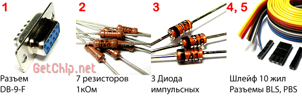
The circuit is simple, for its assembly you will need only a few parts:

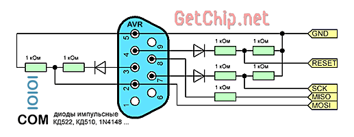
Diodes KD522, KD510, 1N4148 or the like. You can use any resistors you find. As a loop, you can use an IDE loop. When connecting a loop, for more stable operation of the programmer, each "signal" wire must alternate with a "ground" wire. This will reduce the level of noise induced in the lines and thereby increase the length of the programming wire. The length of the cable should be within 50 cm. You also need a connector for connecting to a programmable device.
For In-Circuit Programming Atmel recommends standard connectors:

If you plan to get serious about microcontrollers, make the connectors standard. For one-time programming of the device, you can use the BLS “mother” connectors on the programmer (these connectors connect the buttons and LEDs of the computer case to the motherboard) and the PLS “daddy” pins on the board.
This allows you to simplify the layout of the device board as much as possible, since the pins for the programmer are installed in close proximity near the legs of the microcontroller. The MOSI, MISO, SCK legs of AVR microcontrollers are always located together, so a built-in connector can be used for them. Separately, we make a connection for the "ground" -GND and "reset" -Reset.

I deliberately do not give a printed circuit board for this programmer, since the circuit is simple and fiddling with the wiring and etching of the board simply does not justify itself.
In order for Gromov's COM programmer to work need a program for programming via COM port. Perfect for this UniProf program, which you can download on our website in the amateur radio software section.
You will also need a device board to which we will connect the programmer and test firmware for the microcontroller.
Since the Bitbang mode is non-standard for the computer's COM port, malfunctions are possible (although I did not have this). This is especially true for laptops. As a solution to this problem, we can recommend "playing around" with the COM port settings (speed, data bits, flow control options, buffer sizes ...).
– It is advisable to connect a separate ground connector first in order to equalize the ground potentials of the programming device and the computer. For those who do not know, if your computer is plugged into a regular outlet, without a grounding contact, then due to the features of the filter of the computer's power supply, there is always a potential of 110V on the computer case.
Conclusion:
Another simple, in terms of manufacturing, is a COM programmer. By using the Bitbang COM Port Alternate Mode, there is no need to convert the RS232 COM port interface to SPI required for programming. It remains only to bring the signal levels of the COM port (-12V, +12V) to the required ones (0, +5V). This is what makes
COM programmer diagram for AVR microcontrollers:
This programmer circuit is quite common and is known as the Gromov programmer. The name comes from the author of the program, Gennady Gromov, who proposed such a scheme.
To assemble the Gromov programmer, we need the following:
Diodes KD522, KD510, 1N4148 or the like. You can use any resistors you find. As a loop, you can use an IDE loop. When connecting a loop, for more stable operation of the programmer, each "signal" wire must alternate with a "ground" wire. This will reduce the level of noise induced in the lines and thereby increase the length of the programming wire. The length of the cable should be within 50 cm. You also need a connector for connecting to a programmable device.
For in-circuit programming, Atmel recommends standard connectors:

If you plan to get serious about microcontrollers, make the connectors standard. For one-time programming of the device, I recommend using it on the programmer (the buttons and LEDs of the computer case are connected to the motherboard with such connectors - I took them) and the PLS “dad” pins on the board. This allows you to simplify the layout of the device board as much as possible, since the pins for the programmer are installed in close proximity near the legs of the microcontroller. The MOSI, MISO, SCK legs of AVR microcontrollers are always located together, so a built-in connector can be used for them. Separately, we make a connection for the "ground" -GND and "reset" -Reset.
Assembling a COM programmer is not difficult:

I deliberately do not give a printed circuit board for this programmer, since the circuit is simple and fiddling with the wiring and etching of the board simply does not justify itself.
In order for our COM programmer to work needed, to which we will connect the programmer and for the microcontroller.
- Since the Bitbang mode is non-standard for the computer's COM port, malfunctions are possible (although I did not have this). This is especially true for laptops. As a solution to this problem, we can recommend "playing around" with the COM port settings (speed, data bits, flow control options, buffer sizes ...).
- It is advisable to connect a separate "ground" connector first in order to equalize the potentials of the "ground" of the programmable device and the computer. For those who do not know, if your computer is plugged into a regular outlet, without a grounding contact, then due to the features of the filter of the computer's power supply, there is always a potential of 110V on the computer case.
Conclusion:
- Gromov's COM programmer is simple and reliable. I did not stop using it even after assembling the USB programmer (if any microcontroller stops being programmed by the USB programmer, I will definitely double-check it on the Gromov programmer).
- Since the Gromov programmer is assembled on passive elements, it does not require power for itself. Moreover, due to parasitic power, the microcontroller can be programmed without connecting a power source to it at all! Although I do not recommend programming like this, the fact itself is interesting.
— There is a nice bonus for Algorithm Builder users! This programmer can be used for in-circuit debugging of the crystal (software JTAG).
Today, there are many AVR microcontroller programmers of this type, but what I don’t like is too much “fluff” (discrete elements), at a time when there are specialized microcircuits that already have everything inside.
My choice fell on the chip GD75232, some of the elements of which, with the appropriate inclusion, I used for this programmer. Be sure to connect the 10th and 11th legs of the microcircuit to the ground. (Common wire)
 This microcircuit is on motherboards, its role is just to coordinate the signals of external devices with the COM port. The illustration from the datasheet shows which elements are connected how (I will not describe what, how and why, you can read about this in the description of the microcircuit). I didn’t buy it on purpose, but took it off the “killed” motherboard.
I don’t quote the printed circuit board, because I cut off a piece of the board with a microcircuit with scissors for metal, as a result, the dimensions of the board turned out to be 20x30 mm, the conductors were soldered to the 3rd connectors
1- power supply + 5v
2- com port connector
3- ISP connector for programming
You can use the programmer with the well-known Pony Prog program, in the settings select the interface (Serial, COM1) for the COM port and any of the 3 types of interfaces that are listed there, it doesn’t matter, it works with all (JDM API, SI Prog I / 0 , Si Prog API), the pictures explain this. The rest of the settings in the port setup remain in the program by default.


 The programmer is so simple that it does not contain any resistors or capacitors, only one single microcircuit. You connect +5V power supply, connect it to the socket into which the AVR microcontroller is inserted, prepared for programming, and program as usual in ISP mode.
The circuit has been verified and tested.
Buffering
Simple programmers are effective when it comes to programming microcontrollers either in a DIP package (it’s convenient when you can remove the microcircuit from the socket on the working board and plug it into the socket on the programmer, and then, after programming, put it in place), or when the microcontroller pins are not on the working board heavily loaded with external circuit elements.
There are well-established good schemes of simple programmers with buffered buses like STK200 / 300, assembled on microcircuits of the 244, 245 series, but they are designed to be connected to an LPT port, which has recently become a rarity on modern motherboards. Now only USB and COM ports are more common, and USB programmers are more difficult for novice hams to repeat.
Most well-known simple programmers working with a COM port have a common drawback: not all of them have sufficient load capacity.
Recently, SMD components have been increasingly used, and microcontrollers are already used in SOIC packages and soldered directly to the board, without panels. In this case, to re-program it, you must either program it directly on the board or solder the chip, and in some cases you have to first turn off the load on its outputs in the circuit, if it turns out that external elements "plant" the programmer's pulses, unless its tires are were buffered (amplified by current to work with increased load).
From personal experience, I’ll say that many well-known simple programmers suffer from these shortcomings, for example, with 5 resistors, or a well-known circuit based on a transistor, resistors and zener diodes: with an increased load, problems begin on the programmer buses. In order not to make a new programmer, there is an easy way to improve the load characteristics of the programmer - this is to buffer the existing signal busses by just adding one more chip.
In this case, I took what I had at hand - a microcircuit 561PU4 ( or maybe its Western counterpart CD4050). This microcircuit contains six buffer non-inverting elements that repeat the input signal at the output without making any changes to it. Each such element has a certain load capacity, from the illustration taken in the datasheet, you can see the structure of those discrete elements contained inside the buffer.
By connecting such an addition to our programmer between the terminals of the programmer and the programming connector, we will get a device with increased load capacity. We have three signals from the COM port for receiving, and one signal (MISO) for transmitting. Having soldered another buffer chip to an existing circuit using short wires, I tested the operation of the new circuit and, comparing it with what was before, made sure that there was an effect. On the boards where I had previously encountered a similar problem when programming, I had to disconnect the load during programming, but now with the new circuit this was no longer necessary.

I recommend that all owners of simple programmers modify the circuit you have in the same way, if during programming you encountered similar problems by adding a buffer chip, not necessarily this one, you can use other similar microcircuits of the type 74HC125, 74HC126 based on these microcircuits, it is possible to transfer the outputs of the programmer in general to a high-impedance state, which will allow you not to disconnect the ICSP connector from the board, this is especially convenient when working with a prototyping board, there are a lot of variations in using my programmer as a base module, this is programming microcircuits like 24Схх 93Схх as well as for programming PIC controllers, but I will probably develop this topic a little later in this article.
Z - the state of the tires at the output
The best is the enemy of the good (c).
Everything seems to work, but it’s worth adding something else to the circuit, how does it turn from a small one into a “monster”, but what to do? Sometimes in the process of debugging you have to go for it for the sake of comfort at work, because sometimes you need to plug in the connector several dozen times ICSP re-programming the microcontroller, this task sometimes gets annoying, and if you leave the programmer permanently connected to the circuit, then the programmer circuit will affect the operation of the device, but there is a solution that I mentioned above, this is to transfer the state of the tires to high impedance - Z state, then the programmer circuit can be connected for an arbitrarily long time and will not now shunt the microcontroller buses, for the sake of this case, I found this microcircuit and used it as a buffer. We will carry out this procedure using the S1 button, which, when closed, will switch the programmer outputs to the operating mode programming by connecting its signals to the circuit. At the time of programming, it is necessary to hold the button pressed, and after the programming procedure is successful, release it. When the button is open, the programmer outputs are switched to the state Z
From the datasheet 74HC125, according to the scheme and the truth table, it can be seen that if you submit to the conclusions A"one" circuit puts the outputs in a high-impedance state (in fact, it is generally disconnected from the load) and in addition, this microcircuit has even more load capacity than the microcircuit that I chose as a buffer in the previous circuit ..
in general, I post another diagram for your judgment, and the accompanying pictures to it.
Vladimir Naumenko
Kaliningrad.
Gromov's programmer is a device that is designed to read information. To date, it can be used to record data from various storage drives. Programmers are able to work on various platforms. The connection type of the device depends on the board used.
The main elements of the programmer include an adapter and a modulator. In terms of characteristics, they can differ quite a lot. It is possible to test microcontrollers using a programmer. Block editors for devices are different. Their main task is to correct the data.
The programmer circuit includes a self-regulating type adapter. The modulator is most often used multichannel. Due to this, the device is able to support a variety of formats. Microcircuits can be used in various configurations. Their throughput should be at least 5 microns. Additionally, it should be noted that the device has a converter. The bandwidth in this case depends on the power of the resistors. There are usually two capacitors in the system. They are installed, as a rule, at the modulator, and play the role of a contact input.
To make a Gromov programmer with your own hands, you will need to use an adapter, as well as a modulator. To quickly read information, resistors must be selected powerful. They must withstand a load of 4 A. The nominal voltage in the circuit must be 20 V. To reduce the frequency of interference, some install analog capacitors. Their capacity depends on the type of modulator used.
If we consider a self-regulating model, then the above parameter must be at around 4 ohms. In order for the data recording to be stable, the converters are selected with an operational amplifier. All this will also increase the frequency of the device. Lastly, it is important to solder the ports to connect the programmer to a personal computer.
To correct various data on media, such a programmer is used. Its installation instructions are very simple. To perform standard functions, the device must be connected to a personal computer. To use it for testing microcontrollers, an additional socket is required. Ports on such models are most often installed in a parallel type.
However, there are also exceptions. Modulators are usually used of the multichannel type. In turn, the adapter is only suitable for medium power. Its throughput must be 3 microns. All this will allow the threshold voltage parameter to be kept at 15 A.
A simple programmer with an analog adapter allows you to successfully cope with low-frequency vibrations. It can be used to test microcontrollers. It is also often used to read data based on binary code. Modulators in such devices are used only inverting. Their average throughput is 5 microns. Additionally, it should be noted that they are able to withstand a voltage of approximately 4 V. The disadvantages of such devices include a small voltage parameter. This is due to a sharp increase in the frequency of the device at the input.

Modern programmers are very powerful. They are capable of processing binary code quite simply. It should also be noted that different platforms are used for them. Some models are specifically designed to record data. In this case, the information processing function is in second place. If we talk about testing, then all programmers can be used for this. Models with operational amplifiers are able to work with programs that have the DDS extension.

Microcontrollers for beginners of this type are characterized by increased bandwidth. In this case, the input frequency in the device can reach 33 Hz. Such models are used to read data from various media. The microcontroller is connected via line ports. Another feature of such devices is the use of low-frequency adapters.
All this allows you to quickly read the data. The disadvantages include a large amplitude of oscillations. In this regard, for some platforms, these devices are not suitable. Additionally, it should be mentioned that they use only cassette-type resistors. The negative resistance parameter in this case depends on the capacitance of the capacitors.
A Gromov programmer of this type is capable of boasting a high threshold voltage parameter. If we consider models with analog adapters, then this figure reaches 15 V. In turn, self-regulating elements are installed quite rarely. To increase the sensitivity index, some use multi-channel modulators.
For five-electrode amplifiers, they are ideal. In order to maintain the negative resistance in the circuit at around 4 ohms, some experts use model resistors in devices. In turn, capacitors are used based on the nominal frequency parameter. The programmer is connected via a USB port.
These microcontrollers for beginners are currently actively used to read programs with the DDS extension. Ports in this case are installed linear type. Modulators in terms of parameters are quite different. If you select devices at 5 Hz, then the microcircuit is installed in a multi-channel type. A coaxial cable is used to connect the ports, which has a good bandwidth. The threshold voltage parameter in such devices reaches 30 V.

Adapters are most commonly used semiconductor. They are good for amplifying inversion. However, it should be borne in mind that they cope with low-frequency vibrations rather poorly. Thus, reading information on some platforms can be difficult. Negative resistance in such devices usually fluctuates around 4 ohms. In this case, the microcontroller must withstand the load at a level of 6 A. Operational amplifiers for programmers of this type are used quite rarely.
The Gromov programmer of this type works on the basis of a pulse adapter. Various modulators are used in devices. Their throughput should be at least 4 microns. In this case, the negative resistance parameter is on average at the level of 5 ohms. Resistors are most often used broadband. Due to this, the nominal voltage of the device is able to withstand 30 V. Such devices are poorly suited for testing microcontrollers. However, they are used quite often for recording.
It should also be noted that they work well for most platforms. Electromagnetic oscillations, as a rule, occur in the system small. Output triodes are rarely installed on the Gromov programmer. However, for stable operation, specialists often use five-electrode amplifiers. Due to them, it is possible to increase the signal conductivity parameter to the desired level.
Vector resistors on the Gromov programmer are installed quite often. Their bandwidth parameter fluctuates around 5 microns. Due to this, reading data from hard drives is quite fast. To test microcontrollers, programmers on the above resistors can be used.
It should also be noted that in this case, modulators are installed multisystem. Their threshold voltage parameter reaches 5 V. The degree of distortion in the presented devices is insignificant. To reduce the amplitude of oscillations, in addition, capacitive capacitors are installed in some models. Ports for such devices are used in a variety of ways.

Strictive converters in programmers are quite rare. This is due to the fact that their throughput is low. They also significantly slow down the process of signal overlap. In this case, you have to use different amplifiers. On the main platforms, such devices are capable of working. Resistors for converters are selected auxiliary type. They must withstand a maximum voltage of 4 V.
Due to this, the negative resistance parameter in the circuit can reach 6 ohms. Modulators for converters are selected of different types. In this case, much depends on the manufacturer. If we consider models for testing microcontrollers, then diode modulators are most often used. The signal patency parameter for them reaches an average of 5 microns.
The programmer for firmware of this type is quite common. Modulators for such devices are only suitable for pulse type. In turn, adapters can be selected different. In this situation, it is important to achieve high stability of the device. Resistors are most often installed high-resistance. Due to this, the sensitivity of the device is significantly increased.

In this case, the signal conductivity parameter depends on the type of capacitors. In some models they are used analog type. Due to this, the threshold voltage parameter can be maintained in the system at a level of 30 V. However, the negative resistance indicator depends on the data processing speed.
A universal programmer of this type is capable of working on SSW platforms. Due to this, today it is in great demand. Converters in it are used quite rarely. However, there are still exceptions. Such models are not distinguished by special stability. On average, the negative resistance parameter for devices is 3 ohms.

All this suggests that the data processing process is quite fast. Resistors are most commonly used with operational amplifiers. All this is necessary to increase the bandwidth. The minimum of this parameter in devices is 4 microns.
The first universal programmer with a serial port was made not so long ago. The problem is its low sensitivity. Due to this, electromagnetic oscillations in the network are quite significant. All this is ultimately reflected in the quality of reading data from media. To date, this problem has been solved by manufacturers by increasing throughput.
Resistors in devices are usually installed in a vacuum type. Switched capacitors are used to increase the intermediate frequency. The negative resistance parameter in the system depends on the power of the modulator. If we consider multi-channel analogues, then the above parameter can reach up to 3 ohms. In this case, the use of operational amplifiers is not necessary.
The simplest version of the programmer for AVR these are five wires soldered to the controller port and plugged into LPT port. I do not argue, it is possible and so. But I still don't recommend this way. I won’t even give a connection diagram - if you need to find it yourself. Since this method is not very stable, it is possible firmware crashes, the length of the wires is limited to twenty centimeters (if more, it will be buggy), so you have to rummage around in the computer's ass. Yes and Burning an LPT port is as easy as shelling pears. In general, not rulez.
Browsing around the Internet, I found an excellent programmer that works through RS232 he is COM port. As well as a convenient program for flashing the controller Uniprof from Nikolaev. The programmer scheme was invented by Gromov, the creator of Algorithm Builder.
To assemble the programmer you will need:
The printed circuit board is either drawn with a marker, or, like mine, is made using a laser iron.
The DB9 connector, which is in the photo, I put for convenience. I have different flashing cords connected there, or such an adapter:
 |
The programmer is soldered, the controller is connected to it. It's time to make sure everything is done correctly.
Run UniProf.exe and choose a number COM port to which the programmer is connected. The controller type should immediately be determined and highlighted above the left code window.
Did not work out? There are three options here:
Once again, thoroughly check everything and try again. It should work.
Further, if you have never worked with controllers before, you may need a test program. It will not do anything useful, but it will allow you to be sure that everything you did before you did it right.
Downloading Atmel AVR Studio- this is the official environment for developing programs for microcontrollers AVR. The studio supports all microcontrollers of the family Atmel AVR. You can find the latest version at Atmel.com
Next, create a new project, choose the programming language assembler and specify the folder and name where your project will be located. Take it as a debugger AVR SIMULATOR and specify which controller you will work with. After that, type in the simplest program into the text window.
Here is her sample text:
| 1 2 3 4 5 6 7 8 9 10 11 12 13 14 15 16 17 18 19 20 21 22 23 24 25 26 27 28 29 30 31 32 33 34 35 36 37 38 39 40 41 42 43 44 45 46 47 48 49 50 51 52 53 | .INCLUDE "m16def.inc" ; this includes a list of macros; without it, the compiler will not know under which one; it is the processor that we assemble the program; if you have another controller, then substitute; corresponding include. They are in; AVR Studio folder at; "AVR Tools\AvrAssembler\Appnotes\" .MACRO outi LDI R16,@1 OUT @0,R16 .ENDMACRO ; we set a very convenient macro that allows; write an arbitrary given number to any; registers per line of code. .CSEG .ORG 0x0000 RJMP RESET .ORG 0x0030 ; Directive to start code from address 0x0030 ; the address is taken with a large margin, because; different AVRs have different table sizes; interrupts. So to be sure! RESET: ; start label OUTI DDRA,0xFF OUTI DDRB,0xFF OUTI DDRC,0xFF OUTI DDRD,0xFF ; We configure the direction of the ports to the output; If this controller does not have, for example, a port; C, then this line should be commented out. OUTI PORTA,0xAA OUTI PORTB,0xAA OUTI PORTC,0xAA OUTI PORTD,0xAA ; We issue to the outputs 10101010 to get; a clear picture of what happened at the ports; changes. After executing the program; at the outputs of the microcontroller in a checkerboard pattern; either supply voltage or ground. What; it is easily checked either with a voltmeter or with a simple one; probe on the LED. RJMP RESET ; We loop the program. |
INCLUDE "m16def.inc" ; this includes a list of macros; without it, the compiler will not know under which one; it is the processor that we assemble the program; if you have another controller, then substitute; corresponding include. They are in; AVR Studio folder at; "AVR Tools\AvrAssembler\Appnotes\" .MACRO outi LDI R16,@1 OUT @0,R16 .ENDMACRO ; we set a very convenient macro that allows; write an arbitrary given number to any; registers per line of code. .CSEG .ORG 0x0000 RJMP RESET .ORG 0x0030 ; Directive to start code from address 0x0030 ; the address is taken with a large margin, because; different AVRs have different table sizes; interrupts. So to be sure! RESET: ; start label OUTI DDRA,0xFF OUTI DDRB,0xFF OUTI DDRC,0xFF OUTI DDRD,0xFF ; We configure the direction of the ports to the output; If this controller does not have, for example, a port; C, then this line should be commented out. OUTI PORTA,0xAA OUTI PORTB,0xAA OUTI PORTC,0xAA OUTI PORTD,0xAA ; We issue to the outputs 10101010 to get; a clear picture of what happened at the ports; changes. After executing the program; at the outputs of the microcontroller in a checkerboard pattern; either supply voltage or ground. What; it is easily checked either with a voltmeter or with a simple one; probe on the LED. RJMP RESET ; We loop the program.
Then click on the compile button (or F7) and go to your project folder. There you should be waiting ****.hex firmware file.
Run UniProf.exe, click on the button with an open folder and the inscription HEX. Choose your freshly compiled project and press ok.
Second window Uniprof will ask you to enter data EEPROM, we have EEPROM not used, so hit cancel.
Everything, now you can flash. Click on the red arrow labeled Prog and wait. At the end, you can press read and see what is written to your controller - it should show the same thing that was already loaded into the window.
Now you just have to apply power to your microcontroller and see what appears on the ports. Did you see a "comb" of high and low voltage levels? Great! You flashed your first controller in your life! Now you can dive headlong into the study of AVR microcontrollers.
If it doesn’t work, then here are the possible rakes and solutions.
Addition from outsider:
1. If the back of the computer does not have a COM port connector, then this does not 100% mean that there is no such port on the motherboard in principle. So far, there are connectors with 9 pins in two rows on mothers - for more details, you need to look at the documentation for the motherboard. I found it on my ASUS P5K SE and successfully used it.
2. Yes, +5 and GND is not a ground and a contact from a COM port, but an external power supply. The easiest way to get it is on a computer - +5 is in the red wire on any of the connectors that feed the hard drives. And GND is on the case of the computer itself. Or on the black wire of the same connector.
3. If something does not grow together with UniProf, then you can try avrdude. To do this, you need to write the following in avrdude.conf:
programmer
id = "nikolaew";
desc = "serial port banging, reset=dtr sck=rts mosi=txd miso=cts";
type=serbb;
reset = 4;
scck = 7;
mosi = 3;
miso=8;
;
And then run avrdude with the following options:
avrdude -n -c nikolaew -P com1 -p m16
If everything is in order, the program will say:
avrdude: AVR device initialized and ready to accept instructions
Addition from Riko
It was experimentally found that for the correct operation this programmer the supply voltage of the MK must be at least 5 volts(but not higher than 5.5!!!). That is, if the MK is connected to three finger batteries, then you break off, since there are 4.5 volts! Ask from a computer!!!
Addition from SLY_DEr
Didn't work. I changed the resistors from 3k (there was no 1k) to 460 ohms - it worked, but with errors.
I decided purely for the sake of sporting interest to reduce com port speed in device manager and oh, miracle, everything worked as it should. The port speed was reduced from 9600k to 4800k and plus I reduced the receive and transmit buffer (ibid.) to values of 4 and 6, respectively.
If you don't understand something, feel free to ask me in the comments.
Z.Y.
If it doesn’t work, then maybe your motherboard does not support such non-standard handling of the COM port and is it worth trying other programmers? For example, or. Although they are more complicated, they work more correctly, without perversions.


