So, you've decided to learn how to program pic controllers. First, let's talk about what you need to work with these controllers.
The controller works according to a certain program, which must somehow get into it. Typically, a program in machine code, ready to be written to the controller, is called firmware. Therefore, you need some kind of device that will write (in slang they usually say upload or flash) the program into the controller. This device is called a programmer. We will talk more about programmers and uploading programs later, in the last part of our epic (when there is already something to upload), but for now, let’s take it in order - how to write this program.
The program for the controller is, as I already said, a set of machine codes written in a file with the extension “hex” (), which must be uploaded to the controller using a programmer. The controller does not understand any other language. Therefore, a special program is needed that will translate program text written in any programming language into machine codes. The most convenient in this regard are integrated development environments (IDEs), since they can not only translate program text into machine code, but also simulate its operation. Moreover, the simulation can be carried out step by step, and you can observe the state of the registers or even change their state at will. In short, integrated environments, in addition to compilation itself (translation into machine codes), provide excellent opportunities for debugging a program.
There are many IDEs, as well as programmers. Personally, I use MPLAB and recommend it to you, for the simple reason that MPLAB is an IDE from the manufacturer of PIC controllers, Microchip, and therefore has excellent support (including in Russian, which is especially nice). From the official Microchip website you can download this package itself and a detailed description of how to work with it. If you haven’t found it or it’s difficult to search, it’s true that this is no longer the latest version.
The description in Russian explains everything: from installation and configuration to removal. In most cases, the entire installation consists of running setup and answering a couple of questions, such as where to install drivers and the like, I’ll just add that in order to avoid glitches, you need to install the package in a folder so that only English letters are in the path ( and not to something like C:\Programs\PIC\MPLAB). In general, it is better not to use the Cyrillic alphabet in paths to files or in file names, otherwise glitches are possible.
MPLAB allows you to write programs in two languages: SI and Assembly. The Internet is simply bursting with squabbles between SI guys and assemblers, who are foaming at the mouth to prove to each other which language is better. I consider myself an assembler, so naturally I’ll tell you why Assembler is better.
The assembler is a set of elementary commands executed by the controller. Each command is interpreted into machine code completely unambiguously, and the result of its execution and execution time are always the same. That is, if you have a listing in assembly language, then you can say exactly what the controller is doing at each moment in time and how exactly the desired result is achieved.
A program in the SI language (and indeed in any high-level language) is already a set of commands not from the controller, but from the corresponding language. During compilation, each such command is replaced by a set of commands for the controller, but with what exact set of commands it is replaced - you no longer know this, only the developer of the programming language knows this. Accordingly, it is impossible to understand exactly how the controller performs the desired action.
In short, in the case of a high-level language, you study how some guy called his ways of implementing the functions you need and by what rules they should be written. In this case, we can draw the following analogy: you want to talk to a Chinese person, but they tell you: “Chinese is too difficult a language, but there is one uncle in Bulgaria who lived in China for 20 years and learned it perfectly. And the Bulgarian language and Russian are very similar and Russian people understand it intuitively, so learn Bulgarian, and your uncle will translate."
In the case of assembler, you learn the controller itself and the rules by which you need to talk to the controller. At the same time, the controller has only a few dozen commands that fit on one sheet of paper and can be easily glanced at at a glance.
Hopefully by now you've already made your choice of programming language, so let's move on.
What needs to be done in MPLAB to get the desired firmware? As I already said, read the details in the MPLAB IDE manual, it’s in Russian and everything is clear there (if it’s not clear, go to the forum), I’ll just briefly list the most basic things and give some recommendations.
So, we have installed MPLAB, we want to write a program for the controller in it and get ready-made firmware.
First you need to create a project. For each project, I recommend creating a separate folder, because, firstly, the project may contain several files, and, secondly, MPLAB itself will create several more auxiliary files (*.lst, *.err, *.cod, *. bkx). If several projects are in one folder, then you can easily get confused which files belong to which project. In short, we create a new folder for the project, then launch MPLAB and select the menu Project -> New Project…
In the window that appears, in the explorer on the right, select our folder, on the left side (in the field under the inscription File Name) write the name of the future project, for example my1.pjt (don’t forget to specify the extension), and click OK.
A window appears with the title Edit Project. This is a project manager, which specifies the project parameters (which files and libraries need to be connected to the project, what stone will be used, whether simulation will be used, and much more). Find the input field with the name Development Mode. To the right of this field there is a button Change... Click.
A window with the name opens Development Mode, in which we see a bunch of tabs. On the tab Tools put a tick next to MPLAB SIM Simulator(it’s a sin not to use the simulator for debugging), in the input field Processor select the controller with which we will work. On the tab Clock We indicate what frequency the generator will have. Click OK. We don’t pay attention to the error and warning, they just tell us that they can’t create .hex yet (well, that’s right, we don’t even have a program yet) and that if the settings change, we need to recompile the project again (we’ve never compiled it before) .
In the input field Language Tool Suite choose Microchip.
Click the button with the name Add Node… In the window that appears, in the explorer on the right, select the project folder, in the input field on the left write the name of the file with the text of the assembler program, for example my1.asm (don’t forget to specify the extension), and click OK. That's it, now we have connected the my1.asm file to the project (indicated that the program text will be in this file).
This is where we finish with the Edit project - click OK.
Now you need to actually create a file with the program text (in the project manager we simply indicated that the text will be in such and such a file, but in fact this file has not yet been created). To do this, go to the menu File and select the item New. An editor window named Untitled1 will open. Selecting a menu File -> Save As…, in the explorer on the right we indicate the project folder, in the input field File Name we write the file name that we specified in the project manager, that is, in our example it will be my1.asm. If everything is done correctly, the title of the editor window will change from Untitled1 to \path\my1.asm.
That's all! Now all that remains is to type the program text in the editor window and compile the project (menu Project->Build All) and, if there are no errors in the program (which is very rare the first time), then ready-made firmware (a file with a hex extension) will appear in the project folder, which can be uploaded to the controller.
This MK is widespread and is often found in retail sales. If you are in Moscow, then you should go to “Chip and Dip” - there you can buy it for about 350 rubles. I strongly recommend buying it in a DIP package (wide), fortunately there is one. For initial experiments and tests, this is the best option. If you suddenly purchase it in a PLCC package, then there will be a whole bunch of problems with its use - the pitch of the flat leads of 1.27 mm is not the most convenient option.

So, we decided on MK. In the files for this article you can find a complete guide to this MK. It’s now clear what to buy, but for now let’s write a program so that it would be clear what to do with it next and how to “sew it” into this MK.
We launch the MPLAB program (which we installed in previous articles). Select a menu item Project -> Project Wizard. In the window that opens, click Further.

In the drop-down list of available MCUs, select PIC16F877. Click Further.

Here we need to select a compiler that will process our program code. You must select the item HI-TECH PICC Toolsuite in the dropdown list Active Toolsuite. This is the same C language compiler that we installed in the last article. Click Further.

Give the project a name, for example, TestPIC and specify the project directory. There are two tricks here. First, MPLAB does not create a separate folder for the project itself and will place all files directly in the directory you specified. Second, and perhaps most importantly, MPLAB does not understand Russian letters in the path name. It will create a project, but while the program is running, especially when saving and opening files, such “glitches” will arise that you will be left wondering what’s wrong for a long time. Therefore, the path to the project folder should not contain Russian names. Click Further.

Here you can add any ready-made files to the project, but we don’t need this option yet. Click Further.

Here I think everything is clear. Click Ready.

The project has been prepared, but it is still empty. Click File -> New. A new window will appear with the title Untitled. Next, select File -> Save As.... Provide a file name, for example, TestPIC.c and go to your project folder. Be sure to check the box Add File to Project.

Now we place the following code below in the open window of the TestPIC.c project file (the entire project can be found in the files for this article).
#include
You're probably wondering what the result of this code will be. The following will happen: 8 LEDs are connected to the MK. When you turn on the power, the LEDs will begin to blink in the form of a “wave” (it’s better to see this, fortunately there aren’t that many left). Let's take a closer look at the code itself.
First comes the familiar include statement, which includes the header file with all the necessary macro definitions. Next comes another preprocessor directive __CONFIG, which contains a hexadecimal number characterizing a set of special options and properties that characterize the operation of the MK. We will return to this point later in this article. Let's go straight to the beginning of the main() function - the entry point into the actual executable code of the program. Next comes an operation with some T0IE. Specifically, this line means that it is necessary to disable interrupts from the timer when the MK is running. TOIE is the address of a special register defined using #define in the pic.h file, which is responsible for this operation (and in general, if you see in the code strange previously undefined variables written in uppercase in the code, then these are probably symbolic names of the MK registers) . Line GIE=0; - prohibits the processing of any interrupts globally throughout the entire microcontroller. We will not use interrupts for our simple example, because... We simply don't need them.
TRISB=0; - means that the I/O port B The PIC16F877 MK will work as an output, i.e. You can now connect a load to it, which can supply 0 or +5V from the MK (this load will be LEDs). In the next line we put the number 0 in port B - i.e. All pins on this port configured for output will have zero voltage. Next comes a construction from the while operator, and with such a parameter that some programmers who are accustomed to writing in C for a PC will be slightly surprised - this is, they say, an endless loop, the program will freeze. But this is exactly what we need. MK cannot do nothing, he must constantly do something. Therefore, for MK, running a program in an endless loop is a vital necessity. Then comes the operator to increase by 1 the number located in port B. Let us explain a little. If you write PORTB=0xFF; - then all port pins will have 1. If PORTB=0x0; - for all 0. (I think this should be clear). The construction of the for loop operator, apparently, does not do any “smart” work and is only needed to organize a time delay. If we remove this section of the code, then we simply will not notice how the voltage on the LEDs changes (it will be very quickly).

What do they mean? Let's go in order.
It's time to compile the code. Run Project -> Build All. This will start compiling the project and a window like this will appear with a wonderful entry at the end of BUILD SUCCEEDED.

Now, if you look in our project folder, you should see a file there TestPIC.hex- the result of all our labors. It contains special code, generated from our writings in C, for loading into the MK memory. To move on, we need a programmer with which we will write our program into the MK. It's time to move on to the next article, where the issue of making your own programmer is discussed.
© Ivanov Dmitry
April 2007
In 2006, I had a desire to master assembler for PIC microcontrollers. The decision to master PIC was not formed by chance. There are only 35 assembler commands to start with. You can memorize them in a few days by applying them in practice, when writing your own program. Or simply learn it using the datasheet on any of the PIC controllers. Fortunately, some of the documentation is available in Russian.
Well, the first design is, of course, a clock. And it’s not difficult (at least it seemed so to me at the beginning) and it’s easy to find a use for a clock or timer both at home and at work. The only obstacle that I had to face was the lack of clear and consistently presented information on directly programming methods.
There are many sites on the Internet with microcontroller topics, but often this information is laid out in the form of a sort of vinaigrette, which is very difficult to understand with zero experience in programming chips.
After launching the “first project on a microcontroller” circuit - blinking the LED - a frantic search for useful information began. And quite by accident, while scouring the network in search of information according to the next scheme from the magazine "Radio" (Denisov's frequency meter), I came across the website of Evgeniy Korabelnikov.
I can’t say that my search ended there. I came up with some approaches myself, and my own code, as a rule, is always better than the one invented by someone else.
But I have not yet found a more consistent and methodical presentation of questions on the structure of microcontrollers, options for protocols for exchanging PIC information with external devices (indicators, sensors), working with memory chips and much more.
Evgeniy is an Author with a capital A, he managed to organize and translate a huge amount of material into a normally readable text, making it understandable and accessible, even for those who have never encountered programming before.
If you need a quick start and assembly language programming for PIC controllers, then I recommend Evgeniy Aleksandrovich’s website.
Introduction
1. Prepare the tools. Making a programmer and working with it.
2. What is a microcontroller and how does it work.
3. PIC16F84A command system.
4. What is a program and the rules for its preparation. An example of creating a program for a self-oscillating multivibrator. Directives. Schematic diagram of a multivibrator
5. Integrated design environment MPLAB IDE and work in it.
6. What's next?
7. An example of creating a program (beginning).
8. Example of creating a program (continued).
9. Work in the simulator. Debugging the program.
10. How to track program execution
11. Interrupts. Stack. An example of program development with interruptions.
12. Organization of a calculated transition. Working with EEPROM data memory.
13. Flags. Working with flags. How does a digital comparator work? Transfer and loan.
14. An example of using the C flag in a three-byte adder. Cyclic shift. Multiplication operation.
15. Introduction to the principle of constructing a dynamic display subroutine. Indirect addressing.
16. Converting binary numbers to BCD. Final formation of the text of the dynamic display subroutine.
17. Counting principle. Working with timer TMR0. The principle of installing groups of counting commands in the program text.
Conclusion
Finally, today we have time to introduce you to another family of microcontrollers - these are microcontrollers PIC.
These microcontrollers are also very well-known, are installed in many devices and have long gained very strong interest among radio amateurs.
The developer of this family is the company Microchip, which is also very famous and its products are in demand all over the world.
Studying this series of controllers is a very difficult question. I started doing this a long time ago, but I only got the hang of the line just now. Lately, I have slightly accelerated the process of studying PIC microcontrollers thanks to your requests in groups and chats, to which I could not help but respond.
Therefore, I note that we will program the PIC MK in the C language. We will decide which programming environment and compiler we will choose a little later, but in the meantime, in this lesson we will have a brief introduction to the controllers themselves, their architecture and their varieties.
For example, the AVR controllers we are still working with are 8-bit, while the STM controllers we are studying are 32-bit.
PIC controllers are also divided by bit depth.
First line are 8-bit PIC controllers. Their model names begin with the prefix PIC10/PIC12/PIC16.
This line is also divided into 3 families.
1. BASELINE— this architecture is present in PIC10 controllers. It differs from the more powerful series in the number of pins (from 6 to 28) and in its low cost.
2. MID-RANGE— PIC12/PIC16 microcontroller cores have this architecture. The number of pins in this series has been increased (from 6 to 64), they are slightly more expensive, but in addition to the 35 machine instructions supported by the BASELINE series, they have 14 additional instructions (optimized for the C language compiler). Also, this series has increased productivity by 50%, they have a deeper and improved hardware stack, increased memory capacity and some other delights that we will get acquainted with later, since, most likely, we will begin the process of studying microcontroller programming with this series PIC.
3. 8-bit PIC18 microcontrollers- this is an improved series of controllers, there are many other peripherals on board, the number of pins from 18 to 100, performance 16 MIPS, support for NanoWatt technology, the presence of a programmable generator.
Second line- these are 16-bit controllers PIC. They are prefixed with PIC24F and PIC24H. These are already more powerful controllers. Unlike the first line, a machine command is no longer executed in 4 clock cycles of the generator, but in 2. Also, the peripherals are even more expanded in terms of bus types, direct access to DMA memory (for PIC24H), and an expanded set of instructions. There are also many other features.
Third line- these are 32-bit controllers. Their prefix is already PIC32. The clock frequency of such controllers is up to 120 MHz, and for the new MZ series - up to 200 and even higher. For example, I have a development board on which a PIC32MZ2048EFH064 controller is installed, which has a clock frequency of 252 megahertz. Also here the core performance has been further increased. This family is built on the MIPS32® core, which, in addition to high performance, is also characterized by low energy consumption.
In general, these are the brief characteristics of the currently existing PIC controllers. If we take it by name, then there are a lot of names, to suit every taste, as they say.
Just like the AVR and STM32 controllers we reviewed, as well as the ones we are considering, PIC controllers operate in approximately the same way. A program is written, assembled into machine code that is understandable to the arithmetic-logical device of the controller, loaded (flashed or uploaded) into the controller and then ensures operation according to a certain algorithm. The main interface used to flash these controllers is ICSP, designed for in-circuit programming. We will get to know it in more detail when we flash these controllers.
Let's take a little look at memory organization in PIC controllers. Since we will start studying the PIC family with simpler 8-bit ones (the principle from simple to complex has not been canceled by anyone), we will look at the memory organization of this series.
First, let's look at the block diagram of the controller using the example of MK PIC16F84A(click on the picture to enlarge the image)
In the upper left corner, the FLASH memory module immediately catches your eye, in which the controller program (firmware) is usually stored. And in the upper right corner we see EEPROM memory, which is already used to store data. These two types of memory are non-volatile and are not erased after the controller is turned off and reset. But this memory is not fast, so when the program starts, the code is distributed into RAM memory (RAM), which is already fast and is intended for the functioning of the controller during operation. Therefore, we will now look at this memory in a little more detail.
The PIC controller's RAM is divided into program memory and data memory.
This is how the program memory of the controller is organized PIC16F84A

The microcontrollers in this series have a program counter capable of addressing 8K x 14 words of program memory and a 14-bit program memory data bus. The entire program memory is divided into 4 pages of 2 kilowords each (0000h-07FFh, 0800h-0FFFh, 1000h-17FFh, 1800h-1FFFh). Well, this is general information, so for those controllers with small memory, moving between these pages will lead to cyclic addressing. Therefore, we must know the memory size of the controller that we want to program. In general, program memory consists of a program counter, a stack of several levels, memory for storing interrupt vectors, and internal program memory.
We will also get to know a little about the organization of RAM allocated for data storage.
The data memory is divided into general purpose registers and special purpose registers. Let's see how the controller data memory is organized PIC16F84A
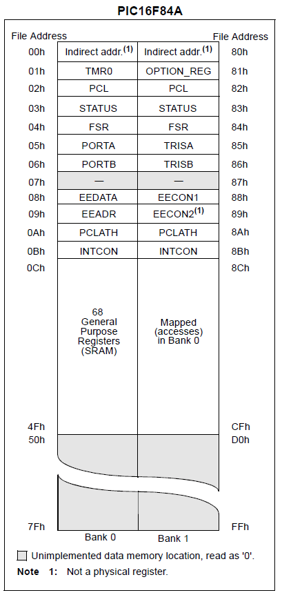
Special Purpose Registers (SFR) are registers that are designed to store strictly designated values and have specific names. We will get to know them gradually when we write some source code that will make extensive use of them.
General Purpose Registers (GPR) are memory cells that have only addresses and are designed to store any data.
Also from the above figure we see that our controller’s data memory is divided into 2 pages (or banks), the transition between which is carried out by setting certain bits in the register STATUS. Therefore, this register is present in both banks and we can access it at any time to change the current memory page.
Addressing can be either direct, indirect or relative, when the address is measured relative to the current address. We may not get acquainted with this, since this task arises for programmers who write programs in assembler.
Accordingly, each controller, in addition to memory, has many other interesting things, including I/O ports. Our PIC controllers are no exception. Let's see the purpose of the controller legs PIC16F84A
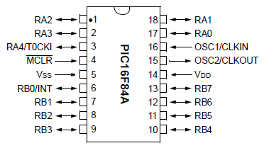
This controller has two ports - port A and port B. From port A, 5 legs are brought out - RA0-RA4, and from port B - all 8 legs RB0-RB7.
Also, the port legs can have other purposes depending on how we configure them. For example, pin 6 or RB0 can at any time turn into a pin for capturing external interrupts, and pin 3 or RA4 can become a pin for clocking a timer from an external generator.
Clocking of the PIC MK can also be carried out either from an external oscillator, or from a quartz resonator, from an internal resistor, and there are also several other options that not all controllers of this family support. In practice, clocking from a quartz resonator is usually used. Most likely, we will also follow this tradition in our future studies.
I think this is where we will finish our acquaintance with PIC controllers. The acquaintance turned out to be brief, but for the first time this will be enough for us. We will encounter more decrypted information when we write our programs. So look forward to the next classes, which promise to be very interesting. We will first get acquainted with the installation of the environment and the compiler, we will study how to work with them, what programming subtleties are present in the settings of various peripherals, as well as in working with it.
Watch VIDEO TUTORIAL (click on the picture)

Post Views: 9,304
Recently I decided to build a device on a PIC microcontroller, but for unknown reasons my Extra-PIC programmer failed. Most likely the microcircuit burned out MAX232, this has already happened once. Without thinking twice, I found on the Internet a simple programmer circuit designed for IC-Prog and working via COM port.
Next, I drilled holes and began soldering the parts. The biggest problem was the zener diodes. I started looking for zener diodes on the board from the CRT monitor. They are labeled on the board as ZD (Zener Diode). Naturally, their markings are unclear and you don’t know where or how to look. To determine how many volts a zener diode is worth, you can assemble a simple circuit.

A voltmeter will show quite accurately how many volts the zener diode is. In this simple way I found zener diodes with approximate nominal values. Instead of 5.6V I installed 6.2V, instead of 12.6V I installed 2 zener diodes in series 6.2+6.2=12.4V
.

The transistor can be installed KT315. I installed it myself S945. Diodes are also any, I unsoldered all 3 pieces. from the diode bridge of the same board from the monitor. The value of the capacitors is also not critical, but they were set at their nominal value.
A little about the red spots on the panels. These legs are not soldered to the panels at all. A fully finished device looks like this:

I decided not to solder all the sockets, because... I just needed to flash it PIC16F628A. After soldering, you need to configure the program. We will flash IC-Prog. , unpack from the archive, All files must be in one folder!
1)
If you are using Windows NT, 2000 or XP, then right-click on the icprog.exe file. " Properties" >> tab " Compatibility" >> Set the checkbox to " Run the program in compatibility mode for:" >>
select "Windows 2000".
2) Let's launch the program. If it is already in Russian, you don’t need anything, go to step 3 .
If the program is in English, then click " Settings" >> "Options" >> tab " Language" >> set language " Russian" and click "Ok".
Agree with the statement " You need to restart IC-Prog now" (click " Ok"). The programmer shell will restart.
3)
Now you need to configure the programmer. Click " Settings" >> "Programmer". Check the settings, select the COM port you are using, click " Ok".

For very fast computers, you may need to increase the I/O Latency setting. Increasing this parameter increases the reliability of programming; however, the time spent on programming the chip also increases.
4) For Windows NT, 2000 or XP users only. Click " Settings" >> "Options" >> select a tab " Are common" >> check the box " On NT/2000/XP driver" >> Click " Ok" >> if the driver has not been installed on your system before, in the window that appears " Confirm"Click "Ok". The driver will be installed and the programmer shell will restart.
5) Click again " Settings" >> "Options" >> select a tab " I2C" >> check the boxes: " Enable MCLR as VCC" And " Enable block recording". Click " Ok".
6)
"Settings" >> "Options" >> select a tab " Programming" >> uncheck the box: " Check after programming" and check the box " Check during programming". Click " Ok".

Done, now the program is completely ready to work with the programmer. We connect our programmer to COM port, select our microcontroller in the program, open the firmware and program any PIC series MKs. Good luck to everyone in working with the programmer and controllers!
Discuss the article PROGRAMMING PIC CONTROLLERS


