Tester for checking optocouplers
Failure of an optocoupler is a rare situation, but it does happen. Therefore, when soldering a TV for parts, it would not be superfluous to check the PC817 for serviceability, so as not to later look for the reason why the freshly soldered power supply does not work. You can also check the optocouplers that came from Aliexpress, not only for defects, but also for compliance with the parameters. In addition to dummies, there may be specimens with inverted markings, and faster optocouplers may actually turn out to be slow.
The device described here will help determine both the serviceability of the common optocouplers PC817, 4N3x, 6N135-6N137, and their speed. It is based on the ATMEGA48 microcontroller, which can be replaced with ATMEGA88. The parts being tested can be connected and disconnected directly into the included tester. The test result is displayed by LEDs. The ERROR LED lights up when there are no connected optocouplers or their malfunction. If the optocoupler, when installed in its socket, turns out to be working, then the corresponding OK LED will light up. At the same time, one or more TIME LEDs corresponding to the speed will light up. So, for the slowest one, PC817, only one LED will light up - TIME PC817, corresponding to its speed. For fast 6N137, all 4 speed LEDs will be lit. If this is not the case, then the optocoupler does not correspond to this parameter. The speed scale values of PC817 - 4N3x - 6N135 - 6N137 have a ratio of 1:10:100:900.
The tester circuit for checking optocouplers is very simple:

click to enlarge
We connected the printed circuit board for power via a micro-USB connector. For the parts being tested, you can install collet or regular DIP panels. In the absence of such, we simply installed collets.

Microcontroller fuses for firmware: EXT =$FF, HIGH=$CD, LOW =$E2.
Printed circuit board (Eagle) + firmware (hex).
Many of us have often had to deal with the fact that because of one failed part, the whole device stops working. To avoid misunderstandings, you should be able to quickly and correctly check details. This is what I am going to teach you. First, we need a multimeter
Most often, transistors burn out in circuits. At least for me. It is very easy to check their functionality. To begin with, it is worth ringing the Base-Emitter and Base-Collector transitions. They must conduct current in one direction, but not allow it to flow in the opposite direction. Depending on whether the PNP is a transistor or an NPN, they will conduct current to the Base or from the Base. For convenience, we can imagine it in the form of two diodes
It is also worth ringing the Emitter-Collector transition. More precisely, these are 2 transitions. . . Well, other than that, that’s not the point. In any transistor, no current should pass through them in any direction while the transistor is off. If voltage is applied to the Base, then the current flowing through the Base-Emitter junction will open the transistor, and the resistance of the Emitter-Collector junction will sharply drop, almost to zero. Please note that the voltage drop across the transistor transitions is usually not lower than 0.6V. And prefabricated transistors (Darlingtons) have more than 1.2V. Therefore, some “Chinese” multimeters with a 1.5V battery simply cannot open them. Don’t be lazy/stingy to get yourself a multimeter with “Krona”!
Please note that some modern transistors have a diode built in parallel with the Collector-Emitter circuit. So it’s worth studying the datasheet for your transistor if the Collector-Emitter rings in one direction!
If at least one of the statements is not confirmed, then the transistor is not working. But before you replace it, check the remaining parts. Perhaps they are the reason!
A working field-effect transistor should have infinite resistance between all its terminals. Moreover, the device should show infinite resistance regardless of the applied test voltage. It should be noted that there are some exceptions.
If, during testing, you apply the positive probe of the test device to the gate of an n-type transistor, and the negative probe to the source, the gate capacitance will charge and the transistor will open. When measuring the resistance between drain and source, the device will show some resistance. Inexperienced repairmen may mistake this behavior of the transistor for its malfunction. Therefore, before “testing” the drain-source channel, short-circuit all the legs of the transistor to discharge the gate capacitance. After this, the drain-source resistance should become infinite. Otherwise, the transistor is considered faulty.
Please also note that in modern high-power field-effect transistors there is a built-in diode between the drain and source, so the drain-source channel behaves like a regular diode when tested. In order to avoid annoying mistakes, remember the presence of such a diode and do not mistake it for a transistor malfunction. You can easily check this by scrolling through the datasheet for your copy.
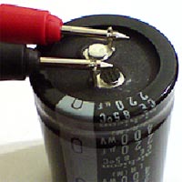
Capacitors are another type of radio components. They also fail quite often. Electrolytic ones die most often; films and ceramics deteriorate somewhat less frequently. . .
To begin with, the boards should be examined visually. Typically, dead electrolytes swell and many even explode. Take a closer look! Ceramic capacitors do not inflate, but they can explode, which is also noticeable! They, like electrolytes, need to be called. They should not conduct current.
Before starting an electronic test of a capacitor, it is necessary to perform a mechanical check of the integrity of the internal contact of its terminals.
To do this, it is enough to bend the leads of the capacitor one by one at a slight angle, and carefully turning them in different directions, as well as slightly pulling towards yourself, to make sure that they are motionless. If at least one terminal of the capacitor rotates freely around its axis, or is freely removed from the housing, then such a capacitor is considered unsuitable and is not subject to further testing.
Another interesting fact is the charge/discharge of capacitors. This can be seen if you measure the resistance of capacitors with a capacity of more than 10 µF. It is also present in smaller containers, but it is not so noticeably expressed! As soon as we connect the probes, the resistance will be a few ohms, but within a second it will increase to infinity! If we swap the probes, the effect will repeat.
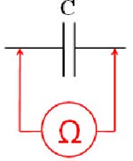
Accordingly, if a capacitor conducts current or does not charge, then it has already passed into another world.

Resistors are the most common on boards, although they do not fail very often. It’s easy to check them, just make one measurement - check the resistance.

If it is less than infinity and not equal to zero, then the resistor is most likely suitable for use. Usually, dead resistors are black - overheated! But black ones can also be alive, although they should also be replaced. After heating, their resistance could change from the nominal one, which would have a bad effect on the operation of the device! In general, it is worth ringing all the resistors, and if their resistance differs from the nominal value, then it is better to replace it. Please note that ±5% deviation from nominal is considered acceptable. . .

In my opinion, it is easiest to check diodes. We measured the resistance, with a plus at the anode, it should show several tens/hundreds of ohms. We measured it with a plus on the cathode - infinity. If not, then the diode should be replaced. . .
Rarely, but still, inductors fail. There are two reasons for this. The first is a short circuit of turns, and the second is an open circuit. It is easy to calculate a break - just check the resistance of the coil. If it is less than infinity, then everything is OK. The resistance of inductors is usually no more than hundreds of ohms. Most often several dozen. . .
The short circuit between turns is somewhat more difficult to calculate. It is necessary to check the self-induction voltage. This only works on chokes/transformers with windings of at least 1000 turns. It is necessary to apply a low-voltage impulse to the winding, and then short-circuit this winding with a gas-discharge light bulb. In fact, loving IN. The pulse is usually applied by lightly touching the CROWN contacts. If the IN eventually blinks, then everything is fine. If not, then there is either a short circuit in the turns or very few turns. . .
As you can see, the method is not very accurate and not very convenient. So first check all the details, and only then sin on the short circuit of the turns!
The optocoupler actually consists of two devices, so it is a little more difficult to test. First, you need to ring the emitting diode. It should, like a regular diode, ring in one direction and serve as a dielectric in the other. Then you need to apply power to the emitting diode and measure the resistance of the photodetector. This can be a diode, transistor, thyristor or triac, depending on the type of optocoupler. Its resistance should be close to zero.
Then we remove the power from the emitting diode. If the resistance of the photodetector has increased to infinity, then the optocoupler is intact. If something is wrong, then it should be replaced!
Another important key element is the thyristor. He also likes to get out of order. Thyristors can also be symmetrical. They're called triacs! It's easy to check both.
We take an ohmmeter, connect the positive probe to the anode, and the negative probe to the cathode. The resistance is infinity. Then we connect the control electrode (CE) to the anode. The resistance drops to about a hundred ohms. Then we disconnect the UE from the anode. In theory, the thyristor resistance should remain low - the holding current.
But keep in mind that some “Chinese” multimeters can produce too little current, so if the thyristor is closed, it’s okay! If it is still open, then remove the probe from the cathode, and after a couple of seconds attach it back. Now the thyristor/triac should definitely close. Resistance is infinity!
If some theses do not coincide with reality, then your thyristor/triac is not working.

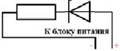
A zener diode is actually a type of diode. This is why it is checked in the same way. Note that the voltage drop across the zener diode, with a plus at the cathode, is equal to its stabilization voltage - it conducts in the opposite direction, but with a larger drop. To check this, we take a power supply, a zener diode and a 300...500 Ohm resistor. We turn them on as in the picture below and measure the voltage on the zener diode.
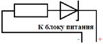
We gradually increase the voltage of the power supply, and at some point, the voltage on the zener diode stops increasing. We have reached its voltage stabilization. If this does not happen, then either the zener diode is not working, or the voltage needs to be increased further. If you know its stabilization voltage, then add 3 volts to it and apply it. Then increase it and if the zener diode does not begin to stabilize, then you can be sure that it is faulty!
Stabilizers are one of the types of zener diodes. Their only difference is that when connected directly - with a plus on the anode, the voltage drop across the stabistor is equal to its stabilization voltage, and in the other direction, with a plus on the cathode, they do not conduct current at all. This is achieved by connecting several diode crystals in series.
Please note that a multimeter with a supply voltage of 1.5V will not physically be able to set the stabilist to, say, 1.9V. Therefore, we turn on our stabistor as in the picture below and measure the voltage on it. You need to apply a voltage of about 5V. Take the resistor with a resistance of 200...500 Ohms. We increase the voltage by measuring the voltage on the stabistor.
If at some point it stopped growing, or began to grow very slowly, then this is its stabilization voltage. He is a worker! If it conducts current in both directions, or has an extremely low voltage drop in direct connection, then it is worth replacing. Apparently it burned down!

Checking various types of cables, adapters, connectors, etc. is quite simple. To do this you need to call your contacts. In a loop, each contact must communicate with one contact on the other side. If the contact does not ring with any other contact, then there is a break in the loop. If it rings with several, then most likely there is a short circuit. The same goes for adapters and connectors. Those with a break or short circuit are considered defective and cannot be used!

There are a great variety of them, they have many pins and perform different functions. Therefore, checking the microcircuit must take into account its functional purpose. It is quite difficult to accurately verify the integrity of the microcircuits. Inside, each represents tens to hundreds of transistors, diodes, resistors, etc. There are hybrids in which there are more than 200,000,000 transistors alone.
One thing is for sure - if you see external damage to the case, spots from overheating, cavities and cracks on the case, loose leads, then the microcircuit should be replaced - it is most likely damaged in the crystal. A heating microcircuit, the purpose of which does not involve heating it, must also be replaced.
A complete check of the microcircuits can only be carried out in a device where it is connected as it should be. This device can be either equipment being repaired or a special test board. When checking microcircuits, the typical inclusion data available in the specification for a specific microcircuit is used.
Well, that's it, no more fluff for you, and less burnt parts!
Using the proposed probe, you can check NE555 (1006VI1) microcircuits and various optodevices: optotransistors, optothyristors, optosimistors, optoresistors. And it is with these radioelements that simple methods do not work, since simply ringing such a part will not work. But in the simplest case, you can test the optocoupler using the following technology:
Using a digital multimeter:

We advise you to spend a little time and make this tester, since optocouplers are increasingly used in various amateur radio designs. And I’m generally silent about the famous KR1006VI1 - they install it almost everywhere. Actually, the 555 chip under test contains a pulse generator, the functionality of which is indicated by the blinking of LEDs HL1, HL2. Next comes the optocoupler probe.

It works like this. The signal from the 3rd leg 555 through resistor R9 reaches one input of the diode bridge VDS1, if a working emitting element of the optocoupler is connected to contacts A (anode) and K (cathode), then current will flow through the bridge, causing the HL3 LED to blink. If the receiving element of the optocoupler is also working, then it will conduct current to the base of VT1, opening it at the moment of ignition of HL3, which will conduct current and HL4 will also blink.

Instructions
If an optocoupler, the serviceability of which is specified under, is soldered into the board, it is necessary to disconnect it, discharge the electrolytic capacitors on it, and then unsolder the optocoupler, remembering how it was soldered.
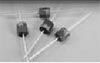
Optocouplers have different emitters (incandescent lamps, neon lamps, LEDs, light-emitting capacitors) and different radiation receivers (photoresistors, photodiodes, phototransistors, photothyristors, phototriacs). They are also pinned. Therefore, it is necessary to find information about the type and pinout of the optocoupler either in a reference book or datasheet, or in the circuit diagram of the device where it was installed. Often, the pinout of the optocoupler is printed directly on the board of this device. If the device is modern, you can almost certainly be sure that the emitter in it is an LED.
If the radiation receiver is a photodiode, connect an optocoupler element to it and connect it, observing the polarity, in a chain consisting of a constant voltage source of several volts, a resistor designed so that the current through the radiation receiver does not exceed the permissible value, and a multimeter operating in measurement mode current at the appropriate limit.
Now put the optocoupler emitter into operating mode. To turn on the LED, pass through it in direct polarity a direct current equal to the rated one. Apply the rated voltage to the incandescent lamp. Using caution, connect the neon lamp or light-emitting capacitor to the network through a resistor with a resistance of 500 kOhm to 1 MOhm and a power of at least 0.5 W.
The photodetector must react to the inclusion of the emitter with a sharp change in mode. Now try turning the emitter off and on several times. The photothyristor and photoresistor will remain open even after the control action is removed until their power is turned off. Other types of photodetectors will react to every change in the control signal. If the optocoupler has an open optical channel, make sure that the reaction of the radiation receiver changes when this channel is blocked.
Having made a conclusion about the state of the optocoupler, de-energize the experimental setup and disassemble it. After this, solder the optocoupler back into the board or replace it with another one. Continue repairing the device that includes an optocoupler.
An optocoupler or optocoupler consists of an emitter and a photodetector separated from each other by a layer of air or a transparent insulating substance. They are not electrically connected to each other, which allows the device to be used for galvanic isolation of circuits.
Instructions
Connect the measuring circuit to the photodetector of the optocoupler in accordance with its type. If the receiver is a photoresistor, use a regular ohmmeter, and the polarity is not important. When using a photodiode as a receiver, connect the microammeter without a power source (positive to the anode). If the signal is received by a phototransistor of the n-p-n structure, connect a circuit of a 2 kilo-ohm resistor, a 3-volt battery and a milliammeter, and connect the battery with the positive side to the collector of the transistor. If the phototransistor has a p-n-p structure, reverse the polarity of the battery connection. To check the photodinistor, make a circuit of a 3 V battery and a 6 V, 20 mA light bulb, connecting it with the positive side to the anode of the dinistor.
In most optocouplers, the emitter is an LED or an incandescent light bulb. Apply the rated voltage to an incandescent light bulb in either polarity. You can also apply alternating voltage, the effective value of which is equal to the operating voltage of the lamp. If the emitter is an LED, apply a voltage of 3 V to it through a 1 kOhm resistor (positive to the anode).
Description, characteristics, Datasheet and methods for testing optocouplers using the example of PC817.
Continuing the topic “Popular radio components for repairs of switching power supplies,” we will analyze one more part - optocoupler (optocoupler) PC817. It consists of an LED and a phototransistor. They are not electrically connected to each other, due to which, based on PC817 it is possible to implement galvanic isolation of two parts of the circuit - for example, with high voltage and with low voltage. The opening of the phototransistor depends on the illumination of the LED. I will discuss how this happens in more detail in the next article, where in experiments, by feeding signals from the generator and analyzing it with an oscilloscope, you can understand a more accurate picture of the operation of the optocoupler.
In other articles I will talk about the non-standard use of optocouplers, first in the role, and in the second. And using these circuit solutions I will build a very simple optocoupler tester. Which does not need any expensive or rare devices, but only a few cheap radio components.
The item is not rare and not expensive. But a lot depends on it. It is used in almost every popular (I don’t mean any exclusive) switching POWER SUPPLY and plays the role of feedback and most often in conjunction with the very popular radio component TL431
For those readers who find it easier to perceive information by ear, we recommend watching the video at the very bottom of the page.
Optocoupler (Optocoupler) PC817
Brief characteristics:
Compact body:
The PC817 is manufactured by Sharp; there are other manufacturers of electronic components that produce analogues, for example:
In addition to the single PC817 optocoupler, other options are available:

To quickly test the optocoupler, I conducted several test experiments. First on the breadboard.

Option on breadboard
As a result, we were able to obtain a very simple circuit for testing the PC817 and other similar optocouplers.

First version of the scheme
I rejected the first option for the reason that it inverted the transistor markings from n-p-n to p-n-p

Therefore, to avoid confusion, I changed the diagram to the following;

Second version of the scheme

The second option worked correctly, but it was inconvenient to solder the standard socket
for a microcircuit

Panel SCS-8

Third version of the scheme
The most successful

Uf is the voltage on the LED at which the phototransistor begins to open.
in my version Uf = 1.12 Volts. 
The result is a very simple design.


