It is impossible to imagine a repairman's workbench without a convenient, inexpensive digital multimeter.
This article discusses the design of digital multimeters of the 830 series, its circuit, as well as the most common faults and methods for eliminating them.
Currently, a huge variety of digital measuring instruments of varying degrees of complexity, reliability and quality are produced. The basis of all modern digital multimeters is an integrated analog-to-digital voltage converter (ADC). One of the first such ADCs suitable for building inexpensive portable measuring instruments was a converter based on the ICL7106 chip, manufactured by MAXIM. As a result, several successful low-cost models of digital multimeters of the 830 series were developed, such as M830B, M830, M832, M838. Instead of the letter M there may be DT. Currently, this series of devices is the most widespread and most repeated in the world. Its basic capabilities: measuring direct and alternating voltages up to 1000 V (input resistance 1 MOhm), measuring direct currents up to 10 A, measuring resistances up to 2 MOhm, testing diodes and transistors. In addition, some models have a mode for audibly testing connections, measuring temperature with and without a thermocouple, and generating a meander with a frequency of 50...60 Hz or 1 kHz. The main manufacturer of multimeters in this series is Precision Mastech Enterprises (Hong Kong).


The basis of the multimeter is the ADC IC1 type 7106 (the closest domestic analogue is the 572PV5 microcircuit). Its block diagram is shown in Fig. 1, and the pinout for execution in the DIP-40 housing is shown in Fig. 2. The 7106 core may have different prefixes depending on the manufacturer: ICL7106, TC7106, etc. Recently, DIE chips have been increasingly used, the crystal of which is soldered directly onto the printed circuit board.

Let's consider the circuit of the M832 multimeter from Mastech (Fig. 3). Pin 1 of IC1 is supplied with a positive 9 V battery supply voltage, and pin 26 is supplied with a negative voltage. Inside the ADC there is a stabilized voltage source of 3 V, its input is connected to pin 1 of IC1, and its output is connected to pin 32. Pin 32 is connected to the common pin of the multi-meter and is galvanically connected to the COM input of the device. The voltage difference between pins 1 and 32 is approximately 3 V in a wide range of supply voltages - from nominal to 6.5 V. This stabilized voltage is supplied to the adjustable divider R11, VR1, R13, and from its output to the input of chip 36 (in mode current and voltage measurements). The divider sets the potential U at pin 36, equal to 100 mV. Resistors R12, R25 and R26 perform protective functions. Transistor Q102 and resistors R109, R110 and R111 are responsible for indicating low battery power. Capacitors C7, C8 and resistors R19, R20 are responsible for displaying the decimal points of the display.

The range of operating input voltages U max directly depends on the level of the adjustable reference voltage at pins 36 and 35 and is
The stability and accuracy of the display readings depends on the stability of this reference voltage.
The display readings N depend on the input voltage U and are expressed as a number
A simplified diagram of a multimeter in voltage measurement mode is shown in Fig. 4.

When measuring DC voltage, the input signal is supplied to R1…R6, from the output of which, through a switch [according to scheme 1-8/1…1-8/2], is supplied to the protective resistor R17. This resistor, in addition, when measuring alternating voltage, together with capacitor C3, forms a low-pass filter. Next, the signal is supplied to the direct input of the ADC chip, pin 31. The common pin potential generated by a stabilized voltage source of 3 V, pin 32, is supplied to the inverse input of the chip.
When measuring alternating voltage, it is rectified by a half-wave rectifier using diode D1. Resistors R1 and R2 are selected in such a way that when measuring a sinusoidal voltage, the device shows the correct value. ADC protection is provided by divider R1…R6 and resistor R17.
A simplified circuit of a multimeter in current measurement mode is shown in Fig. 5.

In the DC current measurement mode, the latter flows through resistors R0, R8, R7 and R6, which are switched depending on the measurement range. The voltage drop across these resistors is fed through R17 to the input of the ADC, and the result is displayed. ADC protection is provided by diodes D2, D3 (may not be installed in some models) and fuse F.
A simplified diagram of a multimeter in resistance measurement mode is shown in Fig. 6. In the resistance measurement mode, the dependence expressed by formula (2) is used.

The diagram shows that the same current from the voltage source +U flows through the reference resistor and the measured resistor R" (the currents of inputs 35, 36, 30 and 31 are negligible) and the ratio of U and U is equal to the ratio of the resistances of resistors R" and R ^. R1..R6 are used as reference resistors, R10 and R103 are used as current-setting resistors. ADC protection is provided by thermistor R18 (some cheap models use regular 1.2 kOhm resistors), transistor Q1 in zener diode mode (not always installed) and resistors R35, R16 and R17 at inputs 36, 35 and 31 of the ADC.
Dial-up mode The dial-up circuit uses IC2 (LM358), which contains two operational amplifiers. An audio generator is assembled on one amplifier, and a comparator on the other. When the voltage at the input of the comparator (pin 6) is less than the threshold, a low voltage is set at its output (pin 7), which opens the switch on transistor Q101, resulting in a sound signal. The threshold is determined by the divider R103, R104. Protection is provided by resistor R106 at the comparator input.
All malfunctions can be divided into manufacturing defects (and this happens) and damage caused by erroneous operator actions.

Since multimeters use dense mounting, short circuits of elements, poor soldering and breakage of element leads are possible, especially those located at the edges of the board. Repair of a faulty device should begin with a visual inspection of the printed circuit board. The most common factory defects of M832 multimeters are shown in the table.
The serviceability of the LCD display can be checked using an alternating voltage source with a frequency of 50.60 Hz and an amplitude of several volts. As such an alternating voltage source, you can take the M832 multimeter, which has a meander generation mode. To check the display, place it on a flat surface with the display facing up, connect one probe of the M832 multimeter to the common terminal of the indicator (bottom row, left terminal), and apply the other probe of the multimeter alternately to the remaining terminals of the display. If you can get all segments of the display to light up, it means it is working.
The malfunctions described above may also appear during operation. It should be noted that in the DC voltage measurement mode, the device rarely fails, because Well protected from input overloads. The main problems arise when measuring current or resistance.
Repair of a faulty device should begin with checking the supply voltage and the functionality of the ADC: stabilization voltage of 3 V and the absence of breakdown between the power pins and the common terminal of the ADC.
In current measurement mode when using the V, Q and mA inputs, despite the presence of a fuse, there may be cases where the fuse burns out later than the safety diodes D2 or D3 have time to break through. If a fuse is installed in the multimeter that does not meet the requirements of the instructions, then in this case the resistances R5...R8 may burn out, and this may not be visually visible on the resistances. In the first case, when only the diode breaks down, the defect appears only in the current measurement mode: current flows through the device, but the display shows zeros. If resistors R5 or R6 burn out in voltage measurement mode, the device will overestimate the readings or show an overload. If one or both resistors burn completely, the device does not reset to zero in voltage measurement mode, but when the inputs are shorted, the display resets to zero. If resistors R7 or R8 burn out, the device will show an overload in the current measurement ranges of 20 mA and 200 mA, and only zeros in the 10 A range.
In resistance measurement mode, damage typically occurs in the 200 Ohm and 2000 Ohm ranges. In this case, when voltage is applied to the input, resistors R5, R6, R10, R18, transistor Q1 may burn out, and capacitor C6 may break through. If transistor Q1 is completely broken, then when measuring resistance the device will show zeros. If the breakdown of the transistor is incomplete, a multimeter with open probes will show the resistance of this transistor. In voltage and current measurement modes, the transistor is short-circuited with a switch and does not affect the multimeter readings. If capacitor C6 breaks down, the multimeter will not measure voltage in the ranges of 20 V, 200 V and 1000 V or significantly underestimate readings in these ranges.
If there is no indication on the display when there is power to the ADC or visually noticeable burnout of a large number of circuit elements, there is a high probability of damage to the ADC. The serviceability of the ADC is checked by monitoring the voltage of a stabilized voltage source of 3 V. In practice, the ADC burns out only when a high voltage is applied to the input, much higher than 220 V. Very often, in this case, cracks appear in the compound of the unpackaged ADC, the current consumption of the microcircuit increases, which leads to its noticeable heating .
When a very high voltage is applied to the input of the device in voltage measurement mode, a breakdown may occur in the elements (resistors) and on the printed circuit board; in the case of voltage measurement mode, the circuit is protected by a divider across resistances R1.R6.
For cheap models of the DT series, long leads of parts can short-circuit to the screen located on the back cover of the device, disrupting the operation of the circuit. Mastech does not have such defects.
The stabilized voltage source of 3 V in the ADC in cheap Chinese models can in practice produce a voltage of 2.6.3.4 V, and for some devices it stops working even at a supply voltage of 8.5 V.
DT models use low quality ADCs and are very sensitive to the integrator chain ratings of C4 and R14. In Mastech multimeters, high-quality ADCs allow the use of elements of similar values.
Often in DT multimeters, when the probes are open in the resistance measurement mode, the device takes a very long time to reach the overload value (“1” on the display) or does not set at all. You can “cure” a low-quality ADC chip by reducing the value of resistance R14 from 300 to 100 kOhm.
When measuring resistances in the upper part of the range, the device “overwhelms” the readings, for example, when measuring a resistor with a resistance of 19.8 kOhm, it shows 19.3 kOhm. It is “cured” by replacing capacitor C4 with a capacitor of 0.22...0.27 µF.
Since cheap Chinese companies use low-quality unpackaged ADCs, there are frequent cases of broken pins, while it is very difficult to determine the cause of the malfunction and it can manifest itself in different ways, depending on the broken pin. For example, one of the indicator pins does not light up. Since multimeters use displays with static indication, to determine the cause of the malfunction it is necessary to check the voltage at the corresponding pin of the ADC chip; it should be about 0.5 V relative to the common pin. If it is zero, then the ADC is faulty.
An effective way to find the cause of a malfunction is to test the pins of the analog-to-digital converter microcircuit as follows. Another, of course, working, digital multimeter is used. It goes into diode test mode. The black probe, as usual, is installed in the COM socket, and the red one in the VQmA socket. The red probe of the device is connected to pin 26 (minus power), and the black one touches each leg of the ADC chip in turn. Since protective diodes are installed at the inputs of the analog-to-digital converter in reverse connection, with this connection they should open, which will be reflected on the display as a voltage drop across the open diode. The actual value of this voltage on the display will be slightly higher, because Resistors are included in the circuit. All ADC pins are checked in the same way by connecting the black probe to pin 1 (plus the ADC power supply) and alternately touching the remaining pins of the microcircuit. The device readings should be similar. But if you change the switching polarity during these tests to the opposite one, then the device should always show a break, because The input resistance of a working microcircuit is very high. Thus, pins that show finite resistance at any polarity of connection to the microcircuit can be considered faulty. If the device shows a break with any connection of the terminal under test, then this is ninety percent an indication of an internal break. This testing method is quite universal and can be used when testing various digital and analog microcircuits.
There are malfunctions associated with poor-quality contacts on the biscuit switch; the device only works when the biscuit switch is pressed. Companies that produce cheap multimeters rarely coat the tracks under the switch with lubricant, which is why they quickly oxidize. Often the paths are dirty with something. It is repaired as follows: the printed circuit board is removed from the case, and the switch tracks are wiped with alcohol. Then a thin layer of technical Vaseline is applied. That's it, the device is fixed.
With DT series devices, it sometimes happens that alternating voltage is measured with a minus sign. This indicates that D1 has been installed incorrectly, usually due to incorrect markings on the diode body.
It happens that manufacturers of cheap multimeters install low-quality operational amplifiers in the sound generator circuit, and then when the device is turned on, a buzzer is heard. This defect is eliminated by soldering an electrolytic capacitor with a nominal value of 5 μF in parallel with the power circuit. If this does not ensure stable operation of the sound generator, then it is necessary to replace the operational amplifier with an LM358P.
Often there is such a nuisance as battery leakage. Small drops of electrolyte can be wiped with alcohol, but if the board is heavily flooded, then good results can be obtained by washing it with hot water and laundry soap. After removing the indicator and unsoldering the tweeter, using a brush, such as a toothbrush, you need to thoroughly soap the board on both sides and rinse it under running tap water. After repeating the wash 2.3 times, the board is dried and installed in the case.
Most devices produced recently use DIE chips ADCs. The crystal is installed directly on the printed circuit board and filled with resin. Unfortunately, this significantly reduces the maintainability of the devices, because... When an ADC fails, which happens quite often, it is difficult to replace it. Devices with bulk ADCs are sometimes sensitive to bright light. For example, when working near a table lamp, the measurement error may increase. The fact is that the indicator and the device board have some transparency, and light, penetrating through them, hits the ADC crystal, causing a photoelectric effect. To eliminate this drawback, you need to remove the board and, having removed the indicator, cover the location of the ADC crystal (it is clearly visible through the board) with thick paper.
When purchasing DT multimeters, you should pay attention to the quality of the switch mechanics; be sure to rotate the multimeter switch several times to make sure that the switching occurs clearly and without jamming: plastic defects cannot be repaired.
We can no longer live without modern washing machines, because they help us reduce time for housework, and we can spend it usefully communicating with our family. But what if this equipment fails? Should you look for a professional service center or repair it yourself?
Today, open plan kitchen layouts and kitchen-dining room combinations are becoming increasingly popular. This is facilitated by a number of positive aspects: a spacious, bright room, open space makes it possible to be in both rooms, it is very pleasant to cook, especially when you are with family or friends, you can watch your favorite movie with your family while cooking.
The DT-830B multimeter is a Chinese-made device that is used by many. Those who constantly deal with electronics cannot do without such equipment. This article describes what the DT-830B multimeter is. The instructions with a detailed description of the device allow even beginners to use it.
There are many models available that differ in quality, accuracy and functionality.
The device is designed for the following basic measurements:
In addition, the DT-830B multimeter and other related models can perform many additional operations:
Not everyone understands how to measure the necessary parameters with a device. When using the DT-830B multimeter, the operating instructions must be followed exactly. Otherwise, the device may burn out.

The function is necessary when you need to carry out electrical wiring in an apartment or find a break in the home network. Not everyone knows how to use a multimeter in this case, but you just need to set the switch in the resistance measurement sector to the appropriate measurement range. The device has an audible alarm indicating that the circuit is closed. If there is no signal, this means that there is a break somewhere or the circuit resistance value is higher than 50 ohms.
The range of minimum resistance (up to 200 Ohms) is called a short circuit. If you connect the red and black probes, the device should show a value close to zero.
The Chinese-made DT-830B multimeter has the following features when measuring electrical resistance:
The device switches to the DCV sector, divided into 5 ranges. The switch is set to a obviously larger range of values. When measuring voltage powered by a 3 V or 12 V battery, you can set the sector to position “20”. You should not set it to a higher value, since the reading error will increase, and if it is lower, the device may burn out. For rough measurements, if you need accuracy of only up to 1 V, the multimeter can be immediately set to the “500” position. The same is done when the measured voltage is unknown in magnitude. Afterwards, you can gradually switch the range to lower values. The highest measurement level is indicated by the "HV" warning, which lights up in the upper left corner. Large voltage values require caution when working with the device, although as a voltmeter from the DT-830B multimeter it is more reliable than an ammeter or ohmmeter.

It is not necessary to maintain the polarity of the probes for a digital device. If it does not match, this will not affect the value of the readings, and the “-” sign lights up on the left side of the screen.
Installation in the ACV sector is carried out in the same way as in the DCV. 220-380 V can lead to failure of the device if connected incorrectly.
Small currents for electronic circuits are measured in the DCA sector. Voltage measurement is not permitted in these switch positions. In this case, a short circuit will occur.
To measure current values up to 10 A, there is a third socket into which the red probe should be moved. Readings can be taken in just a few seconds. Typically, an ammeter is used to measure the current of electrical appliances. In this case, the device should be used carefully and when measurements are really necessary.
In the reverse direction, the diode should show infinity (one on the left). In the forward direction, the voltage at the junction is 400-700 mV.
In this sector you can also check the serviceability of the transistor. If you imagine it as two back-to-back diodes, you need to check each transition for breakdown. To do this, find out where the base is located. For the pnp type, you need to use a positive probe to find such a pin (base) so that the minus probe shows infinity on the other two (emitter and collector). If the transistor is of the npn type, the base is located with the negative probe. To find the emitter, you need to measure the resistance of its junction, which is always greater than the collector. For a working element it should be in the range of 500-1200 Ohms.
By testing the transitions with a multimeter in the forward and reverse directions, you can determine whether the transistor is working or not.
The device can determine the current gain of the h21 transistor. To do this, just insert its 3 pins into the corresponding sockets of the socket. The display will immediately show the value "h21". To obtain correct results, it is necessary to distinguish between pnp (right side of the socket) and npn (left side) types.
The instructions for the DT-830B multimeter provide a certain number of functions. The models differ slightly from each other, and if desired, you can improve any of them, for example, add measurement of capacitance of the capacitor, temperature and all the other additional functions listed earlier.

The basis of a multimeter is
For an inexpensive small-sized device, the ICL7106 chip is most often used.
When measuring voltage, the signal comes from the switch through resistor R17 to input 31 of the microcircuit. When an alternating voltage is measured, it is rectified through diode D1, after which the signal also passes through the chain to pin 32 of the microcircuit.

The measured direct current is created across the resistors, after which the signal is also supplied to input 32. The microcircuit is protected by a 0.2 A fuse installed at the input.
The device often fails when contacts are lost or turned on incorrectly. First of all, check and change the fuse.
The device works reliably when measuring voltage, since it is well protected at the input from overloads. Failures may occur when measuring resistance or current.
Burnt resistors can be identified visually, and diodes and transistors can be checked using the methods given earlier. A check is made for the absence of breaks and reliability of contacts.
When repairing the device, the power supply is first checked. Then the serviceability of the microcircuit is checked. It should be operational if the voltage at pin 30 is 3 V, and there is no breakdown between the power supply and the common pin of the microcircuit.
When disassembling, do not lose the switch balls, without which it will not be securely fixed.
The power supply of the device changes in cases where the numbers on the display disappear and the measurement results deviate from the approximate known values. A battery image appears on the screen. To replace it, you need to remove the back cover, remove the old one and install a new element.
Using the DT-830B multimeter is very convenient: the battery is changed easily and very rarely. You just need to work with it very carefully. The device can easily be burned if used incorrectly.

MULTIMETER DIAGRAMS
There are currently three main models availabledigital multimeters are dt830, dt838, dt9208 and m932. The first model to appear on our markets dt830.
Digital multimeter dt830
Constant pressure:
Limit: 200mV, resolution: 100µV, error: ±0.25%±2
Limit: 2V, resolution: 1mV, error: ±0.5%±2
Limit: 20V, resolution: 10mV, error: ±0.5%±2
Limit: 200V, resolution: 100mV, error: ±0.5%±2
Limit: 1000V/600V, resolution: 1V, error: ±0.5%±2
AC voltage:
Limit: 200V, resolution: 100mV, error: ±1.2%±10
Limit: 750V/600V, resolution: 1V, error: ±1.2%±10
Frequency range from 45Hz to 450Hz.
D.C:
Limit: 200uA, resolution: 100nA, accuracy: ±1.0%±2
Limit: 2000uA, resolution: 1uA, error: ±1.0%±2
Limit: 20mA, resolution: 10uA, error: ±1.0%±2
Limit: 200mA, resolution: 100uA, error: ±1.2%±2
Limit: 10A, resolution: 10mA, error: ±2.0%±2
Resistance:
Limit: 200Ω, resolution: 0.1Ω, error: ±0.8%±2
Limit: 2kOhm, resolution: 1Ohm, error: ±0.8%±2
Limit: 20kOhm, resolution: 10Ohm, error: ±0.8%±2
Limit: 200kOhm, resolution: 100Ohm, error: ±0.8%±2
Limit: 2000kOhm, resolution: 1kOhm, error: ±1.0%±2
Output voltage on ranges: 2.8V
hFE transistor test:
I, DC: 10µA, Uk-e: 2.8V±0.4V, hFE measurement range: 0-1000
Diode test
Test current 1.0mA±0.6mA, Test U 3.2V max.
Polarity: automatic, Overload indication: “1” or “-1” on the display, Measuring speed: 3 meas. per second, Power: 9V.Price - about 3е.

A more advanced and multifunctional modeldigital multimeter, becamedt838. Along with the usual features, they have addedbuilt-in 1 kHz sinusoidal signal generator.
Digital multimeter dt838
Number of measurements per second: 2
Constant voltage U= 0.1mV - 1000V
Variable voltage U~ 0.1V - 750V
Constant current I= 2mA - 10A
AC frequency range current 40 - 400Hz
Resistance R 0.1 Ohm - 2 MOhm
Input resistance R 1 MΩ
Transistor gain h21 up to 1000
Dialing mode< 1 кОм
Power supply 9V, Krona VC
Price - about 5 cu.

The internal and external filling is almost identical to the dt830 model. A similar feature is the low reliability of moving contacts.

Currently one of the most advanced models isdigital multimeter m932 . Features: automatic range selection and non-contact search for static electricity.
Digital multimeter m932
Digital Multimeter Specifications m932:
DC VOLTAGE Measurement limits 600 mV; 6; 60; 600; 1000 V
Accuracy ± (0.5% + 2 units)
Max. resolution 0.1 mV
In. resistance 7.8 MOhm
1000V input protection
AC VOLTAGE Measurement limits 6; 60; 600; 1000 V
Max. resolution 1 mV
Frequency band 50 - 60 Hz
In. impedance 7.8 MOhm
1000V input protection
DC CURRENT Measurement limits 6; 10 A
Accuracy ± (2.5% + 5 units)
Max. resolution 1 mA
ALTERNATING CURRENT Measurement limits 6; 10 A
Max. resolution 1 mA
Frequency band 50 - 60 Hz
RMS measurement - 50 - 60 Hz
Input protection 10 A fuse
RESISTANCE Measurement limits 600 Ohm; 6; 60; 600 kOhm; 6; 60 MOhm
Accuracy ± (1% + 2 units)
Max. resolution 0.1 ohm
600V input protection
CAPACITY Measurement limits 40; 400 nF; 4; 40; 400; 4000 µF
Accuracy ± (3% + 5 units)
Max. resolution 10 pF
600V input protection
FREQUENCY Measurement limits 10; 100; 1000 Hz; 10; 100; 1000 kHz; 10 MHz
Accuracy ± (1.2% + 3 units)
Max. resolution 0.001 Hz
600V input protection
COEF. PULSE FILLING Measuring range 0.1 - 99.9%
Accuracy ± (1.2% + 2 units)
Max. resolution 0.1%
TEMPERATURE Measuring range - -20°C - 760°C (-4°F - 1400°F)
Accuracy ± 5°C/9°F)
Max. resolution 1°C; 1°F
600V input protection
TEST P-N Max. test current 0.3 mA
Test voltage 1 mV
600V input protection
CIRCUIT RINGING Threshold< 100 Ом
Test current< 0.3 мА
600V input protection
GENERAL DATA Max. displayed number 6000
Linear scale 61 segments
Measurement speed 2 per second
Auto shutdown after 15 minutes
Power supply 9 V type "Krona"
Operating conditions 0°С - 50°С; rel. humidity: no more than 70%
Storage conditions -20°C - 60°C; rel. humidity: no more than 80%
Overall dimensions 150 x 70 x 48 mm
Radio amateurs periodically encounter the problem of multimeter failure. Most often, the problem is that the multimeter was soldered using acid and the contacts simply oxidized. In this case, it is very easy to fix the problem, but there can be a more serious problem, for example (as in my case), having forgotten to discharge the capacitor, they put it into a digital multimeter and want to measure the capacitance, after which the tester refuses to measure anything at all.
Having opened the multimeter, we obviously won’t see anything, since the microcircuit was killed by static. The chip itself will most likely have the numbers 324, as in the photo. Fundamental circuit diagram DT9205A Can.
But since the multimeter is made in China, most likely we will not find any data on this chip. So at first I didn’t find anything, but then I decided to search, entering not all the elements of the microcircuit inscription, but only the numbers. And the result was pleasing - the microcircuit turned out to be lm324, or rather a Chinese copy, only with different letters. It is possible to change it to any other op-amp. If you have a radio store in your city, then you can quickly go there and buy this microcircuit, but if there is no such store (as in my case) or it is far away, and you really need a capacitance meter, then we replace it with any existing microcircuit that contains contains 4 operational amplifiers. If there are no quadruple ones, just install two microcircuits that contain 2 op-amps, as I did at first.

However, it later turned out that with them the multimeter gives an error. This was due to the fact that the gain of my op-amps was different from that of the lm324. But there was nowhere to go, since I already said earlier we don’t have radio stores, and ordering on the Internet is also not the best option - you’ll have to wait a long time for the order to arrive, so I decided to install others. Just a couple of days before the DT9205A multimeter was repaired, an order of five TL074s arrived.

True, I had them in a DIP package so that it would not interfere with closing the lid DT9205A- soldered it with wires.

It is possible that when you change the op-amp, even if it is lm324, the multimeter will show slightly incorrectly. In this case, if the deviation is not very large, then this error is removed by a trimming resistor next to the microcircuit (shown by the red arrow), but since there may be deviations in the value of the capacitor, it is better to measure its capacitance on another multimeter and set yours to the same reading.

And finally, a couple of photos of the work after the renovation.

Enough time has passed since then and the multimeter works without problems. I wish you all creative success! Article author: 13265
Discuss the article REPAIR OF MULTIMETER DT9205

Flux SKF
In any case, no matter how you remove this resistor from the board, there will be tubercles of old solder on the board; we need to remove it using a dismantling braid, dipping it in alcohol-rosin flux. Place the tip of the braid directly on the solder and press it in, heating it with the tip of the soldering iron until all the solder from the contacts is absorbed into the braid.
![]()
Dismantling braid
Well, then it’s a matter of technology: we take the resistor we bought in the radio store, put it on the contact pads, which we freed from solder, press it down with a screwdriver from above and touching the tip of a 25-watt soldering iron, the pads and leads located at the edges of the resistor, solder it in place.

Solder braid - application
The first time it will probably come out crooked, but the most important thing is that the device will be restored. On the forums, opinions about such repairs were divided; some argued that due to the low cost of multimeters, it makes no sense to repair them at all, they say they threw them away and went and bought a new one, others were even ready to go all the way and resolder the ADC). But as this case shows, sometimes repairing a multimeter is quite simple and cost-effective, and any home craftsman can easily handle such repairs. Everyone! AKV.
Currently, a huge variety of digital measuring instruments of varying degrees of complexity, reliability and quality are produced. The basis of all modern digital multimeters is an integrated analog-to-digital voltage converter (ADC). One of the first such ADCs suitable for building inexpensive portable measuring instruments was a converter based on the ICL71O6 chip, produced by MAXIM. As a result, several successful low-cost models of digital multimeters of the 830 series were developed, such as M830B, M830, M832, M838. Instead of the letter M there may be DT. Currently, this series of devices is the most widespread and most repeated in the world. Its basic capabilities: measuring direct and alternating voltages up to 1000 V (input resistance 1 MOhm), measuring direct currents up to 10 A, measuring resistances up to 2 MOhm, testing diodes and transistors. In addition, some models have a mode for audibly testing connections, measuring temperature with and without a thermocouple, and generating a meander with a frequency of 50...60 Hz or 1 kHz. The main manufacturer of multimeters in this series is Precision Mastech Enterprises (Hong Kong).
The basis of the multimeter is the ADC IC1 type 7106 (the closest domestic analogue is the 572PV5 microcircuit). Its block diagram is shown in Fig. 1, and the pinout for execution in the DIP-40 housing is shown in Fig. 2. The 7106 core may have different prefixes depending on the manufacturer: ICL7106, TC7106, etc. Recently, DIE chips have been increasingly used, the crystal of which is soldered directly onto a printed circuit board.

Let's consider the circuit of the M832 multimeter from Mastech (Fig. 3). Pin 1 of IC1 is supplied with a positive 9 V battery supply voltage, and pin 26 is supplied with a negative voltage. Inside the ADC there is a source of stabilized voltage of 3 V, its input is connected to pin 1 of IC1, and the output is connected to pin 32. Pin 32 is connected to the common pin of the multimeter and is galvanically connected to the COM input of the device. The voltage difference between pins 1 and 32 is approximately 3 V in a wide range of supply voltages - from nominal to 6.5 V. This stabilized voltage is supplied to the adjustable divider R11, VR1, R13, and its output is fed to the input of microcircuit 36 (in measurement mode currents and voltages). The divider sets the potential U eg at pin 36, equal to 100 mV. Resistors R12, R25 and R26 perform protective functions. Transistor Q102 and resistors R109, R110nR111 are responsible for indicating low battery power. Capacitors C7, C8 and resistors R19, R20 are responsible for displaying the decimal points of the display.
![]() Rice. 3. Schematic diagram of the M832 multimeter
Rice. 3. Schematic diagram of the M832 multimeter
![]()
![]()
A simplified diagram of a multimeter in voltage measurement mode is shown in Fig. 4. When measuring direct voltage, the input signal is supplied to R1…R6, from the output of which, through a switch (according to the 1-8/1… 1-8/2 scheme), is supplied to the protective resistor R17. This resistor, in addition, when measuring alternating voltage, together with the capacitor SZ, forms a low-pass filter. Next, the signal is supplied to the direct input of the ADC chip, pin 31. The common pin potential generated by a stabilized voltage source of 3 V, pin 32, is supplied to the inverse input of the chip.

When measuring alternating voltage, it is rectified by a half-wave rectifier using diode D1. Resistors R1 and R2 are selected in such a way that when measuring a sinusoidal voltage, the device shows the correct value. ADC protection is provided by divider R1…R6 and resistor R17.

A simplified circuit of a multimeter in current measurement mode is shown in Fig. 5. In the DC current measurement mode, the latter flows through resistors RO, R8, R7 and R6, switched depending on the measurement range. The voltage drop across these resistors is fed through R17 to the input of the ADC, and the result is displayed. ADC protection is provided by diodes D2, D3 (may not be installed in some models) and fuse F.

A simplified diagram of a multimeter in resistance measurement mode is shown in Fig. 6. In the resistance measurement mode, the dependence expressed by formula (2) is used. The diagram shows that the same current from the voltage source +LJ flows through the reference resistor Ron and the measured resistor Rx (the currents of inputs 35, 36, 30 and 31 are negligible) and the ratio of UBX and Uon is equal to the ratio of the resistances of resistors Rx and Ron. R1....R6 are used as reference resistors, R10 and R103 are used as current-setting resistors. ADC protection is provided by thermistor R18 [some cheap models use conventional resistors with a nominal value of 1...2 kOhm], transistor Q1 in zener diode mode (not always installed) and resistors R35, R16 and R17 at inputs 36, 35 and 31 of the ADC.
The dialing circuit uses IC2 (LM358), which contains two operational amplifiers. An audio generator is assembled on one amplifier, and a comparator is assembled on the other. When the voltage at the input of the comparator (pin 6) is less than the threshold, at its output (pin 7) is set, which opens the key on transistor Q101, resulting in a sound signal. The threshold is determined by the divider R103, R104. Protection is provided by resistor R106 at the comparator input.
| Defect manifestation | Possible reason | Troubleshooting |
|---|---|---|
| Check elements C1 and R15 | ||
| Open the connector pins | ||
| When measuring alternating voltage, the instrument readings “float”, for example, instead of 220 V they change from 200 V to 240 V | ||
| Solder the pins of IC2 | ||
| To restore reliable contact you need: Correct the conductive rubber bands; Wipe the corresponding contact pads on the printed circuit board with alcohol; Tin these contacts on the board |
||
The serviceability of the LCD display can be checked using an alternating voltage source with a frequency of 50...60 Hz and an amplitude of several volts. As such an alternating voltage source, you can take the M832 multimeter, which has a meander generation mode. To check the display, place it on a flat surface with the display facing up, connect one probe of the M832 multimeter to the common terminal of the indicator (bottom row, left terminal), and apply the other probe of the multimeter alternately to the remaining terminals of the display. If you can get all segments of the display to light up, it means it is working.
In current measurement mode when using the V, Ω and mA inputs, despite the presence of a fuse, there may be cases where the fuse burns out later than the safety diodes D2 or D3 have time to break through. If a fuse is installed in the multimeter that does not meet the requirements of the instructions, then in this case the resistances R5...R8 may burn out, and this may not be visually visible on the resistances. In the first case, when only the diode breaks down, the defect appears only in the current measurement mode: current flows through the device, but the display shows zeros. If resistors R5 or R6 burn out in voltage measurement mode, the device will overestimate the readings or show an overload. If one or both resistors burn completely, the device does not reset to zero in voltage measurement mode, but when the inputs are shorted, the display resets to zero. If resistors R7 or R8 burn out, the device will show an overload in the current measurement ranges of 20 mA and 200 mA, and only zeros in the 10 A range.
When a very high voltage is applied to the input of the device in voltage measurement mode, a breakdown may occur in the elements (resistors) and on the printed circuit board; in the case of voltage measurement mode, the circuit is protected by a divider across resistances R1 ... R6.
The stabilized voltage source of 3 V in the ADC of cheap Chinese models can in practice produce a voltage of 2.6...3.4 V, and for some devices it stops working even at a supply voltage of 8.5 V.
Often in DT multimeters, when the probes are open in the resistance measurement mode, the device takes a very long time to reach the overload value (“1” on the display) or does not set at all. You can “cure” a low-quality ADC chip by reducing the value of resistance R14 from 300 to 100 kOhm.
When measuring resistances in the upper part of the range, the device “overwhelms” the readings, for example, when measuring a resistor with a resistance of 19.8 kOhm, it shows 19.3 kOhm. “It is treated” by replacing capacitor C4 with a capacitor of 0.22...0.27 µF.
With DT series devices, it sometimes happens that alternating voltage is measured with a minus sign. This indicates that D1 has been installed incorrectly, usually due to incorrect markings on the diode body.
It happens that manufacturers of cheap multimeters install low-quality operational amplifiers in the sound generator circuit, and then when the device is turned on, a buzzer is heard. This defect is eliminated by soldering an electrolytic capacitor with a nominal value of 5 μF in parallel with the power circuit. If this does not ensure stable operation of the sound generator, then it is necessary to replace the operational amplifier with an LM358P.
Often there is such a nuisance as battery leakage. Small drops of electrolyte can be wiped with alcohol, but if the board is heavily flooded, then good results can be obtained by washing it with hot water and laundry soap. After removing the indicator and unsoldering the tweeter, using a brush, such as a toothbrush, you need to thoroughly soap the board on both sides and rinse it under running tap water. After repeating the wash 2…3 times, the board is dried and installed in the case.
Most devices produced recently use DIE chips ADCs. The crystal is installed directly on the printed circuit board and filled with resin. Unfortunately, this significantly reduces the maintainability of the devices, because... When an ADC fails, which happens quite often, it is difficult to replace it. Devices with bulk ADCs are sometimes sensitive to bright light. For example, when working near a table lamp, the measurement error may increase. The fact is that the indicator and the device board have some transparency, and light, penetrating through them, hits the ADC crystal, causing a photoelectric effect. To eliminate this drawback, you need to remove the board and, having removed the indicator, cover the location of the ADC crystal (it is clearly visible through the board) with thick paper.
M830 circuits... The difference is not big DT830 or M830...
Everyone needs to know how to use measuring instruments.
A multimeter is a universal device (in short, “tester”, from the word “test”). There are a lot of varieties. We won’t consider them all. Let’s take the most easily accessible multimeter made in China, the DT-830B.
MULTIMETER DT-830B consists of:
-LCD display
-multi-position switch
- sockets for connecting probes
-panel for testing transistors
-back cover (will be needed to replace the device’s battery, a 9-volt “Krona” type element)
The switch positions are divided into sectors:
OFF/on - device power switch
DCV - DC voltage measurement (voltmeter)
ACV- AC voltage measurement (voltmeter)
hFe - transistor measurement switching sector
1.5v-9v - checking batteries.
DCA - direct current measurement (ammeter).
10A - ammeter sector for measuring large values of direct current (according to instructions
measurements are carried out within a few seconds).
Diode - sector for checking diodes.
Ohm - resistance measurement sector.
DCV sector
On this device, the sector is divided into 5 ranges. Measurements are taken from 0 to 500 volts. We will encounter high DC voltage only when repairing a TV. This device must be operated with extreme caution at high voltages.
When turned to the "500" volt position, the HV warning lights up on the screen in the upper left corner. that the highest level of measurement is turned on and when large values appear you need to be extremely careful.
Typically, voltage measurements are carried out by switching large positions of the range to smaller ones if you do not know the value of the voltage being measured. For example, before measuring the voltage on the battery of a cell phone or car, which says the maximum voltage is 3 or 12 volts, we boldly set the sector to the “20” volt position. If we set it to a lower value, for example, “2000” millivolts, the device may fail. If we set it to high, the device readings will be less accurate.
When you do not know the value of the measured voltage (of course, within the framework of household electrical equipment, where it does not exceed the values of the device), then set the “500” volts to the upper position and take a measurement. In general, you can roughly measure, with an accuracy of one volt, at the “500” volt position.
If greater accuracy is required, switch to the lower position, only so that the value of the measured voltage does not exceed the value at the position of the device switch. This device is convenient in measuring direct current voltage in that it does not require observance of polarity. If the polarity of the probes ("+" - red, "-" - black) does not coincide with the polarity of the measured voltage, a "-" sign will appear on the left side of the screen, and the value will correspond to the measured one.
ACV sector
The sector has 2 positions on this type of device - “500” and “200” volts.
Handle 220-380 volt measurements with great care.
The procedure for measuring and setting positions is similar to the DCV sector.
DCA sector.
It is a direct current milliammeter and is used to measure small currents, mainly in electronic circuits. We won't need it for now.
To avoid damage to the device, do not place the switch on this sector; if you forget and start measuring voltage, the device will fail.
Sector Diode.
One position for checking diodes for breakdown (small
resistance) and to break (infinite resistance). The measurement principles are based on the operation of an Ohmmeter. Same as hFE.
hFE sector
To measure transistors, there is a socket indicating which transistor leg to place in which socket. Transistors of both p-p-p and p-p-p conductivities are checked for breakdown, open circuit, and greater deviation from standard transition resistances.
Digital multimeter M832. Electrical diagram, description, characteristics
It is impossible to imagine a repairman's workbench without a convenient, inexpensive digital multimeter. This article discusses the design of digital multimeters of the 830 series, the most common faults and methods for eliminating them.
Currently, a huge variety of digital measuring instruments of varying degrees of complexity, reliability and quality are produced. The basis of all modern digital multimeters is an integrated analog-to-digital voltage converter (ADC). One of the first such ADCs suitable for building inexpensive portable measuring instruments was a converter based on the ICL71O6 chip, produced by MAXIM. As a result, several successful low-cost models of digital multimeters of the 830 series were developed, such as M830B, M830, M832, M838. Instead of the letter M there may be DT. Currently, this series of devices is the most widespread and most repeated in the world. Its basic capabilities: measuring direct and alternating voltages up to 1000 V (input resistance 1 MOhm), measuring direct currents up to 10 A, measuring resistances up to 2 MOhm, testing diodes and transistors. In addition, some models have a mode for audibly testing connections, measuring temperature with and without a thermocouple, and generating a meander with a frequency of 50...60 Hz or 1 kHz. The main manufacturer of multimeters in this series is Precision Mastech Enterprises (Hong Kong).
Scheme and operation of the device
Rice. 1. Block diagram of ADC 7106
The basis of the multimeter is the ADC IC1 type 7106 (the closest domestic analogue is the 572PV5 microcircuit). Its block diagram is shown in Fig. 1, and the pinout for execution in the DIP-40 housing is shown in Fig. 2. The 7106 core may have different prefixes depending on the manufacturer: ICL7106, TC7106, etc. Recently, DIE chips have been increasingly used, the crystal of which is soldered directly onto the printed circuit board.

Rice. 2. Pinout of ADC 7106 in DIP-40 package
Let's consider the circuit of the M832 multimeter from Mastech (Fig. 3). Pin 1 of IC1 is supplied with a positive 9 V battery supply voltage, and pin 26 is supplied with a negative voltage. Inside the ADC there is a source of stabilized voltage of 3 V, its input is connected to pin 1 of IC1, and the output is connected to pin 32. Pin 32 is connected to the common pin of the multimeter and is galvanically connected to the COM input of the device.
The voltage difference between pins 1 and 32 is approximately 3 V in a wide range of supply voltages - from nominal to 6.5 V. This stabilized voltage is supplied to the adjustable divider R11, VR1, R13, and its output is fed to the input of microcircuit 36 (in measurement mode currents and voltages).
The divider sets the potential U eg at pin 36, equal to 100 mV. Resistors R12, R25 and R26 perform protective functions. Transistor Q102 and resistors R109, R110nR111 are responsible for indicating low battery power. Capacitors C7, C8 and resistors R19, R20 are responsible for displaying the decimal points of the display.

Rice. 3. Schematic diagram of the M832 multimeter
The range of operating input voltages Umax directly depends on the level of the adjustable reference voltage at pins 36 and 35 and is:
The stability and accuracy of the display readings depends on the stability of this reference voltage. The display readings N depend on the UBX input voltage and are expressed as a number:
Let's consider the operation of the device in the main modes.
Voltage measurementA simplified diagram of a multimeter in voltage measurement mode is shown in Fig. 4. When measuring DC voltage, the input signal is supplied to R1...R6, from the output of which, through a switch (according to scheme 1-8/1... 1-8/2), is supplied to the protective resistor R17. This resistor, in addition, when measuring alternating voltage, together with the capacitor SZ, forms a low-pass filter. Next, the signal is supplied to the direct input of the ADC chip, pin 31. The common pin potential generated by a stabilized voltage source of 3 V, pin 32, is supplied to the inverse input of the chip.

Rice. 4. Simplified circuit of a multimeter in voltage measurement mode
When measuring alternating voltage, it is rectified by a half-wave rectifier using diode D1. Resistors R1 and R2 are selected in such a way that when measuring a sinusoidal voltage, the device shows the correct value. ADC protection is provided by divider R1...R6 and resistor R17.
Current measurement
Rice. 5. Simplified circuit of a multimeter in current measurement mode
A simplified circuit of a multimeter in current measurement mode is shown in Fig. 5. In the DC current measurement mode, the latter flows through resistors RO, R8, R7 and R6, switched depending on the measurement range. The voltage drop across these resistors is fed through R17 to the input of the ADC, and the result is displayed. ADC protection is provided by diodes D2, D3 (may not be installed in some models) and fuse F.
Resistance measurement
Rice. 6. Simplified circuit of a multimeter in resistance measurement mode
A simplified diagram of a multimeter in resistance measurement mode is shown in Fig. 6. In the resistance measurement mode, the dependence expressed by formula (2) is used. The diagram shows that the same current from the voltage source +LJ flows through the reference resistor Ron and the measured resistor Rx (the currents of inputs 35, 36, 30 and 31 are negligible) and the ratio of UBX and Uon is equal to the ratio of the resistances of resistors Rx and Ron. R1....R6 are used as reference resistors, R10 and R103 are used as current-setting resistors. ADC protection is provided by thermistor R18 [some cheap models use conventional resistors with a nominal value of 1...2 kOhm], transistor Q1 in zener diode mode (not always installed) and resistors R35, R16 and R17 at inputs 36, 35 and 31 of the ADC.
Dialing modeThe dialing circuit uses IC2 (LM358), which contains two operational amplifiers. An audio generator is assembled on one amplifier, and a comparator on the other. When the voltage at the input of the comparator (pin 6) is less than the threshold, a low voltage is set at its output (pin 7), which opens the switch on transistor Q101, resulting in a sound signal. The threshold is determined by the divider R103, R104. Protection is provided by resistor R106 at the comparator input.
Defects of multimetersAll malfunctions can be divided into manufacturing defects (and this happens) and damage caused by erroneous operator actions.
Since multimeters use dense mounting, short circuits of elements, poor soldering and breakage of element leads are possible, especially those located at the edges of the board. Repair of a faulty device should begin with a visual inspection of the printed circuit board. The most common factory defects of M832 multimeters are shown in the table.
| Defect manifestation | Possible reason | Troubleshooting |
|---|---|---|
| When you turn on the device, the display lights up and then goes out smoothly | Malfunction of the master oscillator of the ADC chip, the signal from which is supplied to the LCD display substrate | Check elements C1 and R15 |
| When you turn on the device, the display lights up and then goes out smoothly. The device works normally when the back cover is removed. | When the back cover of the device is closed, the contact helical spring rests on resistor R15 and closes the master oscillator circuit | Bend or shorten the spring slightly |
| When the device is turned on in voltage measurement mode, the display readings change from 0 to 1 | The integrator circuits are faulty or poorly soldered: capacitors C4, C5 and C2 and resistor R14 | Solder or replace C2, C4, C5, R14 |
| The device takes a long time to reset the readings to zero | Low quality capacitor SZ at the ADC input (pin 31) | Replace the SZ with a capacitor with a low absorption coefficient |
| When measuring resistances, the display readings take a long time to settle | Poor quality of capacitor C5 (automatic zero correction circuit) | Replace C5 with a capacitor with a low absorption coefficient |
| The device does not work correctly in all modes, the IC1 chip overheats. | The long pins of the connector for testing transistors are shorted together | Open the connector pins |
| When measuring alternating voltage, the instrument readings “float”, for example, instead of 220 V they change from 200 V to 240 V | Loss of capacitance of the capacitor SZ. Possible bad soldering of its terminals or simply the absence of this capacitor | Replace the SZ with a working capacitor with a low absorption coefficient |
| When turned on, the multimeter either beeps constantly, or vice versa, remains silent in connection testing mode | Poor soldering of the Yu2 microcircuit pins | Solder the pins of IC2 |
| Segments on the display disappear and appear | Poor contact of the LCD display and the contacts of the multimeter board through the conductive rubber inserts | To restore reliable contact you need: adjust the conductive rubber bands; wipe the corresponding contact pads on the printed circuit board with alcohol; tin the contacts on the board |
The serviceability of the LCD display can be checked using an alternating voltage source with a frequency of 50...60 Hz and an amplitude of several volts. As such an alternating voltage source, you can take the M832 multimeter, which has a meander generation mode. To check the display, place it on a flat surface with the display facing up, connect one probe of the M832 multimeter to the common terminal of the indicator (bottom row, left terminal), and apply the other probe of the multimeter alternately to the remaining terminals of the display. If you can get all segments of the display to light up, it means it is working.
The malfunctions described above may also appear during operation. It should be noted that in the DC voltage measurement mode, the device rarely fails, because Well protected from input overloads. The main problems arise when measuring current or resistance.
Repair of a faulty device should begin with checking the supply voltage and the functionality of the ADC: stabilization voltage of 3 V and the absence of breakdown between the power pins and the common terminal of the ADC.
In current measurement mode when using the V, Ω and mA inputs, despite the presence of a fuse, there may be cases where the fuse burns out later than the safety diodes D2 or D3 have time to break through. If a fuse is installed in the multimeter that does not meet the requirements of the instructions, then in this case the resistances R5...R8 may burn out, and this may not be visually visible on the resistances. In the first case, when only the diode breaks down, the defect appears only in the current measurement mode: current flows through the device, but the display shows zeros. If resistors R5 or R6 burn out in voltage measurement mode, the device will overestimate the readings or show an overload. If one or both resistors burn completely, the device does not reset to zero in voltage measurement mode, but when the inputs are shorted, the display resets to zero. If resistors R7 or R8 burn out, the device will show an overload in the current measurement ranges of 20 mA and 200 mA, and only zeros in the 10 A range.
In resistance measurement mode, damage typically occurs in the 200 Ohm and 2000 Ohm ranges. In this case, when voltage is applied to the input, resistors R5, R6, R10, R18, transistor Q1 can burn out and capacitor Sb can break through. If transistor Q1 is completely broken, then when measuring resistance the device will show zeros. If the breakdown of the transistor is incomplete, a multimeter with open probes will show the resistance of this transistor. In voltage and current measurement modes, the transistor is short-circuited with a switch and does not affect the multimeter readings. If capacitor C6 breaks down, the multimeter will not measure voltage in the ranges of 20 V, 200 V and 1000 V or significantly underestimate readings in these ranges.
If there is no indication on the display when there is power to the ADC or visually noticeable burnout of a large number of circuit elements, there is a high probability of damage to the ADC. The serviceability of the ADC is checked by monitoring the voltage of a stabilized voltage source of 3 V. In practice, the ADC burns out only when a high voltage is applied to the input, much higher than 220 V. Very often, in this case, cracks appear in the compound of the unpackaged ADC, the current consumption of the microcircuit increases, which leads to its noticeable heating .
When a very high voltage is applied to the input of the device in voltage measurement mode, a breakdown may occur in the elements (resistors) and on the printed circuit board; in the case of voltage measurement mode, the circuit is protected by a divider across resistances R1 ... R6.
For cheap models of the DT series, long leads of parts can short-circuit to the screen located on the back cover of the device, disrupting the operation of the circuit. Mastech does not have such defects.
The stabilized voltage source of 3 V in the ADC of cheap Chinese models can in practice produce a voltage of 2.6...3.4 V, and for some devices it stops working even at a supply voltage of 8.5 V.
DT models use low quality ADCs and are very sensitive to the values of the integrator chain C4 and R14. In Mastech multimeters, high-quality ADCs allow the use of elements of similar values.
Often in DT multimeters, when the probes are open in the resistance measurement mode, the device takes a very long time to reach the overload value (“1” on the display) or does not set at all. You can “cure” a low-quality ADC chip by reducing the value of resistance R14 from 300 to 100 kOhm.
When measuring resistances in the upper part of the range, the device “overwhelms” the readings, for example, when measuring a resistor with a resistance of 19.8 kOhm, it shows 19.3 kOhm. It is “cured” by replacing capacitor C4 with a capacitor of 0.22...0.27 µF.
Since cheap Chinese companies use low-quality unpackaged ADCs, there are frequent cases of broken pins, while it is very difficult to determine the cause of the malfunction and it can manifest itself in different ways, depending on the broken pin. For example, one of the indicator pins does not light up. Since multimeters use displays with static indication, to determine the cause of the malfunction it is necessary to check the voltage at the corresponding pin of the ADC chip; it should be about 0.5 V relative to the common pin. If it is zero, then the ADC is faulty.
An effective way to find the cause of a malfunction is to test the pins of the analog-to-digital converter microcircuit as follows. Another, of course, working, digital multimeter is used. It goes into diode test mode. The black probe, as usual, is installed in the COM socket, and the red one in the VQmA socket. The red probe of the device is connected to pin 26 [minus power], and the black one touches each leg of the ADC chip in turn. Since protective diodes are installed at the inputs of the analog-to-digital converter in reverse connection, with this connection they should open, which will be reflected on the display as a voltage drop across the open diode. The actual value of this voltage on the display will be slightly higher, because Resistors are included in the circuit. All ADC pins are checked in the same way by connecting the black probe to pin 1 [plus the ADC power supply] and alternately touching the remaining pins of the microcircuit. The device readings should be similar. But if you change the switching polarity during these tests to the opposite one, then the device should always show a break, because The input resistance of a working microcircuit is very high. Thus, pins that show finite resistance at any polarity of connection to the microcircuit can be considered faulty. If the device shows a break with any connection of the terminal under test, then this is ninety percent an indication of an internal break. This testing method is quite universal and can be used when testing various digital and analog microcircuits.
There are malfunctions associated with poor-quality contacts on the biscuit switch; the device only works when the biscuit switch is pressed. Companies that produce cheap multimeters rarely coat the tracks under the switch with lubricant, which is why they quickly oxidize. Often the paths are dirty with something. It is repaired as follows: the printed circuit board is removed from the case, and the switch tracks are wiped with alcohol. Then a thin layer of technical Vaseline is applied. That's it, the device is fixed.
With DT series devices, it sometimes happens that alternating voltage is measured with a minus sign. This indicates that D1 has been installed incorrectly, usually due to incorrect markings on the diode body.
It happens that manufacturers of cheap multimeters install low-quality operational amplifiers in the sound generator circuit, and then when the device is turned on, a buzzer is heard. This defect is eliminated by soldering an electrolytic capacitor with a nominal value of 5 μF in parallel with the power circuit. If this does not ensure stable operation of the sound generator, then it is necessary to replace the operational amplifier with an LM358P.
Often there is such a nuisance as battery leakage. Small drops of electrolyte can be wiped with alcohol, but if the board is heavily flooded, then good results can be obtained by washing it with hot water and laundry soap. After removing the indicator and unsoldering the tweeter, using a brush, such as a toothbrush, you need to thoroughly soap the board on both sides and rinse it under running tap water. After repeating the wash 2...3 times, the board is dried and installed in the case.
Most devices produced recently use DIE chips ADCs. The crystal is installed directly on the printed circuit board and filled with resin. Unfortunately, this significantly reduces the maintainability of the devices, because... When an ADC fails, which happens quite often, it is difficult to replace it. Devices with bulk ADCs are sometimes sensitive to bright light. For example, when working near a table lamp, the measurement error may increase. The fact is that the indicator and the device board have some transparency, and light, penetrating through them, hits the ADC crystal, causing a photoelectric effect. To eliminate this drawback, you need to remove the board and, having removed the indicator, cover the location of the ADC crystal (it is clearly visible through the board) with thick paper.
When purchasing DT multimeters, you should pay attention to the quality of the switch mechanics; be sure to rotate the multimeter switch several times to make sure that the switching occurs clearly and without jamming: plastic defects cannot be repaired.
Publication: www.cxem.net
See other articles section.Quite recently, I received from a car enthusiast 2 DT-830B testers - they looked completely new. He said that they burned out due to the incorrect connection of the ammeter to the battery in the 10A position, he said that he turned it on in parallel while charging the battery, and first one was damaged, then he bought a second one and it suffered the same fate. I asked for them for myself, because... My tester of the same brand has a worn-out case, and in general it doesn’t handle being dropped from a table very well, so I decided to ask him to give me these two in order to change the case. I got to work, took off the cover and decided to see for myself that it was faulty.
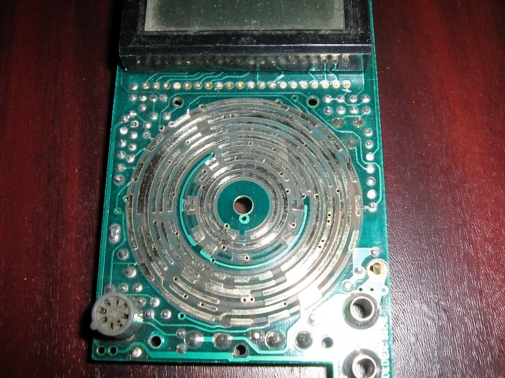
Visually I discovered that one terminal was missing, apparently the battery was taken out without caring about the health of the board. The fuse is intact, the resistors are normal - so to check, I set the position of the voltmeter, connect the probes - the display shows 0.00. Ohmmeter too, ammeter, etc. I decided to remove the board, and here it is:

I found a burnt track near the battery terminal, sometimes the track burns, but the fuse is intact.

I connected it as best I could and started assembling it. I would like to draw special attention of inexperienced home repair enthusiasts to these bearings, which can get lost during quick disassembly, and without them there will be no clear switching.

Assembled - it works. There was a lot of joy, I opened the second one, and there were no bounds to surprise...

As a result, + 2 testers in 25 minutes, having assembled both of them, I checked them for functionality - they function like new!

On the right is my tester and next to it are two - now also mine :) All I have to do is figure out why I need 3 of them now, but that's another story. I wish everyone to be attentive to any equipment before giving up on it, because often repairs involve simple steps to restore contacts.


