Hello, today I will tell you how to make an adjustable power supply based on the lm317 chip. The circuit will be able to produce up to 12 volts and 5 amperes.


Comments (16):
#1 root March 28 2017
Additions have been made to the diagram:
It is better to make up capacitance C1 from several electrolytic capacitors; if you need a high current, then 2 pieces of 4700 μF or more are recommended.
KT819 transistors can be replaced with foreign MJ3001 or others.
#2 Victor September 12 2017
R2 - what type, sp...or. The circuit is not bad! THANK YOU!!!
#3 root September 12 2017
Resistor R2 - variable resistance, any type, power 0.5 W or more. If there is no suitable one with a resistance of 3.3K, then you can install 6.8K or another (up to 10kOhm).
#4 Dmitry October 25 2017
Thank you for the lessons, very useful.
#5 Evgeniy November 25 2017
What about overload/short circuit protection?
#6 root November 26, 2017
In the above circuit there is no protection against short circuit and overcurrent. Without improving the circuit, it would not hurt to install a fuse at its output.
#7 andrius December 15 2017
I assembled the circuit, but somehow the current at the output drops. Trans 300sch 40a I supply 31 volts and at the output with a load of 6 volts 3 volts. Maybe I assembled something wrong. I changed the transistors too - it doesn’t help.
#8 root December 15 2017
Carefully check the entire installation, especially the correct connection of the microcircuit and transistors.
Pinout of the LM317 chip: 
For transistors in plastic and metal cases - KT819 - characteristics and pinout.
#9 andrius December 15 2017
everything has been checked many times. The microcircuit is connected correctly and the transistor is also connected. I also changed the microcircuit and transistors. nothing helps, I don’t even know what else can be done.
#10 Alexander Compromister December 16 2017
Thanks to #root for the mixed internal circuit diagram of the chip: I looked everywhere, but to no avail. For the 12th Krenka it will be similar.
#11 Alexander Compromister December 17 2017
Regarding the internal circuit of LM317: how to replace the current source: probably with two (or more) silicon diodes? Is it possible to replace the transistors on the internal circuit with one composite brand, say, KT827VM? How to replace the operational amplifier? How to build current protection? - And while I was writing the questions, I immediately found the answer: use a field-effect transistor.
#12 root December 17 2017
Alexander, below is a schematic diagram of the LM117, LM317-N microcircuit crystal from the datasheet (website ti.com - Texas Instruments): 
#13 Alexander Compromister December 17 2017
Thank you: it is very reminiscent of the KR142EN circuit from . But there are no denominations.
#14 Igor December 26 2017
Is it possible to use KT827a transistors in the circuit?
#15 Alexander Compromister December 27 2017
To user #Igor: Surely this is possible, however, after the op-amp (see post #8) in the base circuit before the protection circuit, you probably need to include a quenching resistor, the value of which depends on the supply voltage: the main thing is that there is no more than five volts. The Current Protection unit can probably be replaced with a KS147A zener diode.
#16 Andrey February 06, 2018
Hello, I’m assembling a power supply for the first time - I found an old transformer in the garage. I’m trying to make it according to this diagram. Please tell me which leg of the variable resistor goes where.
Current stabilizer for LEDs is used in many lamps. Like all diodes, LEDs have a nonlinear current-voltage dependence. What does it mean? As the voltage increases, the current slowly begins to gain power. And only when the threshold value is reached, the brightness of the LED becomes saturated. However, if the current does not stop increasing, the lamp may burn out.
Correct LED operation can only be ensured thanks to a stabilizer. This protection is also necessary due to the variation in LED voltage threshold values. When connected in a parallel circuit, the light bulbs may simply burn out, since they have to pass an amount of current that is unacceptable for them.
According to the method of limiting the current, devices of linear and pulse type are distinguished.
Since the voltage across the LED is a constant value, current stabilizers are often considered LED power stabilizers. In fact, the latter is directly proportional to the change in voltage, which is typical for a linear relationship.
The linear stabilizer heats up the more the voltage is applied to it. This is his main flaw. The advantages of this design are due to:
More economical devices are stabilizers based on a pulse converter. In this case, power is pumped in portions - as needed by the consumer.
The simplest stabilizer circuit is a circuit built on the basis of LM317 for an LED. The latter are an analogue of a zener diode with a certain operating current that it can pass. Considering the low current, you can assemble a simple device yourself. The simplest driver for LED lamps and strips is assembled in this way.
The LM317 microcircuit has been a hit among novice radio amateurs for decades due to its simplicity and reliability. Based on it, you can assemble an adjustable driver unit and other power supplies. This requires several external radio components, the module works immediately, no configuration is required.
The LM317 integrated stabilizer is like no other suitable for creating simple adjustable power supplies for electronic devices with different characteristics, both with adjustable output voltage and with specified load parameters.
The main purpose is to stabilize the specified parameters. The adjustment occurs in a linear manner, unlike pulse converters.
LM317 is produced in monolithic cases, designed in several variations. The most common model is TO-220, marked LM317T.
Each pin of the microcircuit has its own purpose:

Technical parameters of the stabilizer:
The maximum “bar” of the input voltage should be no more than the specified one, and the minimum should be 2 V higher than the desired output voltage.
The microcircuit is designed for stable operation at a maximum current of up to 1.5 A. This value will be lower if a high-quality heat sink is not used. The maximum permissible power dissipation without the latter is approximately 1.5 W at an ambient temperature of no more than 30 0 C.
When installing a microcircuit, it is necessary to insulate the case from the radiator, for example, using a mica gasket. Also, effective heat removal is achieved by using heat-conducting paste.
The advantages of the LM317 radio-electronic module used in current stabilizers can be briefly described as follows:
Of course, the simplest way to limit current for LED lamps is to connect an additional resistor in series. But this tool is only suitable for low-power LEDs.
To make a current stabilizer you will need:
We assemble the model according to the diagram below:

The module can be used in circuits of various chargers or regulated information security devices.
This option is more practical. LM317 limits the current consumption, which is set by resistor R.

Remember that the maximum current required to drive the LM317 is 1.5A with a good heatsink.
Below is a circuit with an adjustable output voltage of 1.2–30 V/1.5 A.

AC current is converted to DC using a bridge rectifier (BR1). Capacitor C1 filters the ripple current, C3 improves the transient response. This means that the voltage regulator can work perfectly with constant current at low frequencies. The output voltage is adjusted by slider P1 from 1.2 volts to 30 V. The output current is about 1.5 A.
The selection of resistors according to the nominal value for the stabilizer must be carried out according to an accurate calculation with a permissible deviation (small). However, arbitrary placement of resistors on the circuit board is allowed, but it is advisable to place them away from the LM317 heatsink for better stability.
The LM317 chip is an excellent option for use in the mode of stabilization of basic technical indicators. It is distinguished by its simplicity of execution, inexpensive cost and excellent performance characteristics. The only drawback is that the voltage threshold is only 3 V. The TO220 style case is one of the most affordable models, which allows it to dissipate heat quite well.
The microcircuit is applicable in devices:
The stabilizing circuit based on the LM317 is simple, cheap, and at the same time reliable.
Somehow recently I came across a circuit on the Internet for a very simple power supply with the ability to adjust the voltage. The voltage could be adjusted from 1 Volt to 36 Volt, depending on the output voltage on the secondary winding of the transformer.
Take a close look at the LM317T in the circuit itself! The third leg (3) of the microcircuit is connected to capacitor C1, that is, the third leg is INPUT, and the second leg (2) is connected to capacitor C2 and a 200 Ohm resistor and is an OUTPUT.
Using a transformer, from a mains voltage of 220 Volts we get 25 Volts, no more. Less is possible, no more. Then we straighten the whole thing with a diode bridge and smooth out the ripples using capacitor C1. All this is described in detail in the article on how to obtain constant voltage from alternating voltage. And here is our most important trump card in the power supply - this is a highly stable voltage regulator chip LM317T. At the time of writing, the price of this chip was around 14 rubles. Even cheaper than a loaf of white bread.
LM317T is a voltage regulator. If the transformer produces up to 27-28 volts on the secondary winding, then we can easily regulate the voltage from 1.2 to 37 volts, but I would not raise the bar to more than 25 volts at the transformer output.
The microcircuit can be executed in the TO-220 package:

or in D2 Pack housing

It can pass a maximum current of 1.5 Amps, which is enough to power your electronic gadgets without voltage drop. That is, we can output a voltage of 36 Volts with a current load of up to 1.5 Amps, and at the same time our microcircuit will still output 36 Volts - this, of course, is ideal. In reality, fractions of volts will drop, which is not very critical. With a large current in the load, it is more advisable to install this microcircuit on a radiator.
In order to assemble the circuit, we also need a variable resistor of 6.8 Kilo-Ohms, or even 10 Kilo-Ohms, as well as a constant resistor of 200 Ohms, preferably from 1 Watt. Well, we put a 100 µF capacitor at the output. Absolutely simple scheme!
Previously, I had a very bad power supply with transistors. I thought, why not remake it? Here is the result ;-)
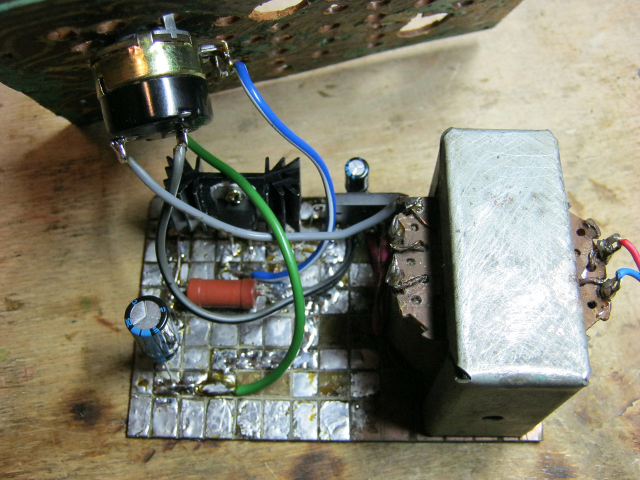
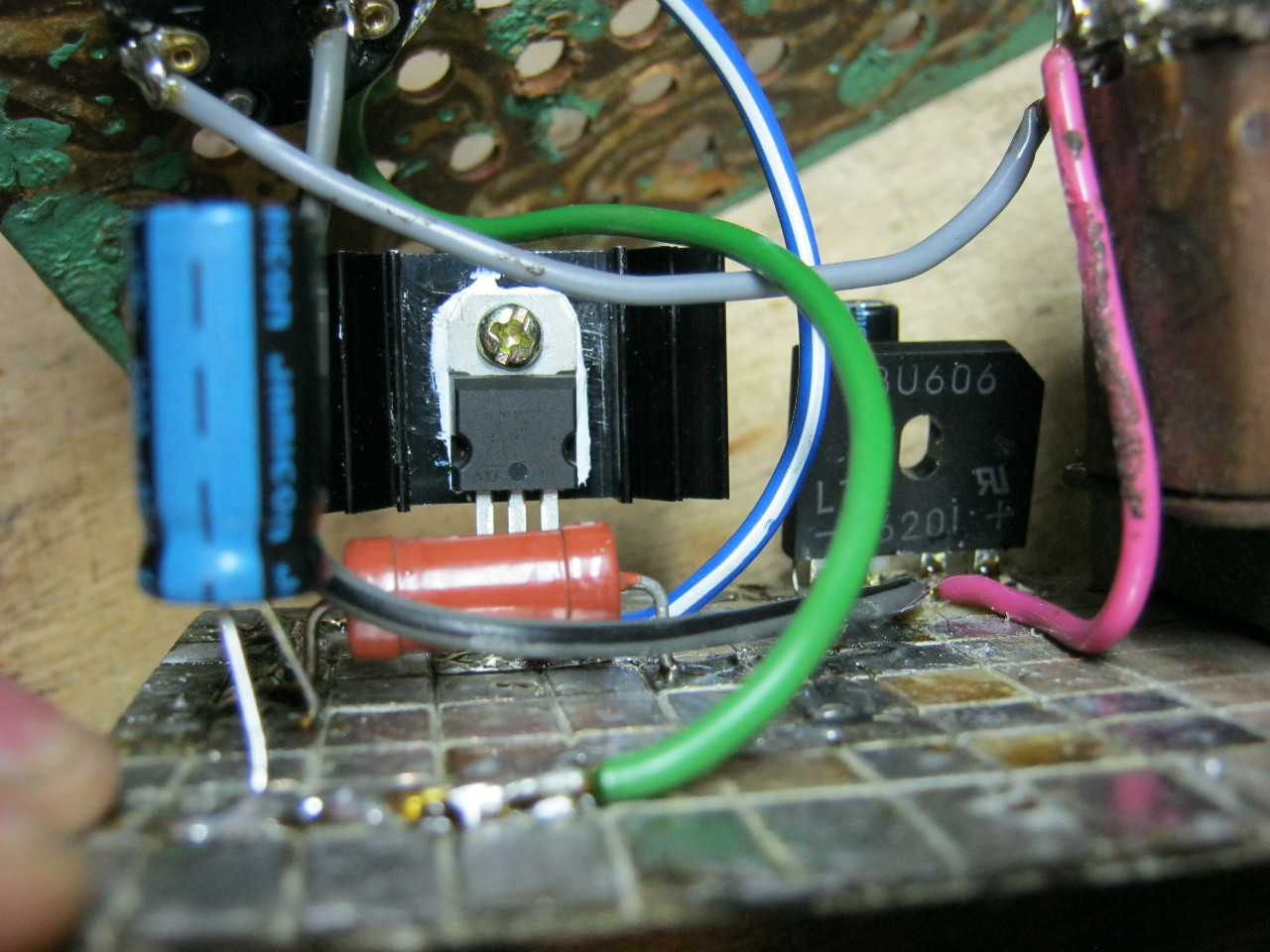
Here we see the imported GBU606 diode bridge. It is designed for a current of up to 6 Amps, which is more than enough for our power supply, since it will deliver a maximum of 1.5 Amps to the load. I installed the LM on the radiator using KPT-8 paste to improve heat transfer. Well, everything else, I think, is familiar to you.
And here is an antediluvian transformer that gives me a voltage of 12 volts on the secondary winding.

We carefully pack all this into the case and remove the wires.

So what do you think? ;-)

The minimum voltage I got was 1.25 Volts, and the maximum was 15 Volts.


I set any voltage, in this case the most common are 12 Volts and 5 Volts
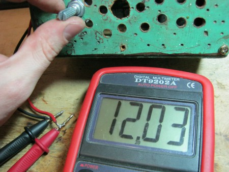

Everything works great!
This power supply is very convenient for adjusting the speed of a mini drill, which is used for drilling circuit boards.

By the way, on Ali you can immediately find a ready-made set of this block without a transformer.

Too lazy to collect? You can buy a ready-made 5 Amp for less than $2:

You can view it at this link.
If 5 Amps is not enough, then you can look at 8 Amps. It will be enough for even the most seasoned electronics engineer:

Lorem Ipsum is simply dummy text of the printing and typesetting industry. Lorem Ipsum has been the industry"s standard dummy text ever since the 1500s, when an unknown printer took a galley of type and scrambled it to make a type specimen book. It has survived not only five http://jquery2dotnet.com/ centuries , but also the leap into electronic typesetting, remaining essentially unchanged. It was popularized in the 1960s with the release of Letraset sheets containing Lorem Ipsum passages, and more recently with desktop publishing software like Aldus PageMaker including versions of Lorem Ipsum.
power unit- This is an indispensable attribute in the amateur radio workshop. I also decided to build myself an adjustable power supply, because I was tired of buying batteries every time or using random adapters. Here is its brief description: The power supply regulates the output voltage from 1.2 Volts to 28 Volts. And it provides a load of up to 3 A (depending on the transformer), which is most often enough to test the functionality of amateur radio designs. The circuit is simple, just right for a beginner radio amateur. Assembled on the basis of cheap components - LM317 and KT819G.
LM317 regulated power supply circuit
List of circuit elements:
Pinout of the microcircuit and transistor
The case was taken from the computer's power supply. The front panel is made of PCB, it is advisable to install a voltmeter on this panel. I haven't installed it because I haven't found a suitable one yet. I also installed clamps for the output wires on the front panel.
I left the input socket to power the power supply itself. A printed circuit board made for surface-mounted mounting of a transistor and a stabilizer chip. They were secured to a common radiator through a rubber gasket. The radiator was solid (you can see it in the photo). It needs to be taken as large as possible - for good cooling. Still, 3 amperes is a lot!


