Free electricity in mini volumes will help you quickly understand the power of free energy. You will need an old fan (aka cooler) from a computer and three neodymium magnets. This simple version of the BTG fuel-free generator is a miniature of large free electricity generators.
As well as a wooden platform (or any one of your choice), as well as a glue gun.


here is the marking


Apply glue to the blade and glue it.

second magnet on the opposite side

glue it the same way

You don’t need to do this! — initially there was a desire to make 4 magnets, but they were larger and heavier, so the cooler engine did not work.
here is the error

and so on in the end - until two large ones peel off.


glue a cooler to it

It’s better to glue it well, otherwise there will be vibration...

glue the lamp to the cooler

here's the end result:


first wire through diode

the second one directly to the light bulb

Pre-peel off two magnets, so it will be easier for you.. you only need to glue two

movement begins


Having found the ideal point for the placement of the magnet, glue it.
Now you can start the perpetual motion machine with a push of your finger...
Ready to repeat this experiment?
Do you believe this is true?
Do you think there is deception here?
That you can become part of a community where there is a knowledge base, in which there is a collection of ready-made instructions for assembling BTG, drawings, diagrams, DISCUSSIONS, and the same enthusiasts.
In the FreeTeslaEnergy community, you can always find friends and like-minded people, fellow free energy enthusiasts.
We have put together a collection of instructions, models, and BTG drawings that you can assemble too. Join the closed community of FreeTeslaEnergy enthusiasts
Community members discuss together the models and assemblies of the authors, looking for those who can assemble a fuel-free energy generator for lighting or heating a house or apartment...
Write below on this page about your experience and what you think about it...
In contact with
In this article I will tell you how to make an engine - a Bedini generator from a computer cooler. This device model is one of the lowest power, but at the same time it is very convenient to use, cheap and easy to manufacture. It is very convenient to conduct experiments with the model. It takes up very little space and is easy to maintain. I will tell you the best, in my opinion, way of making it.
You will need: Transistor 2N3055 TO-3; Diode 1 N 4001 and 1 N 4007; Resistor 47 Ohm - 100 Ohm (I recommend 51 Ohm, 1W -2W); 1kΩ trim resistor (I recommend R-17N1-B1K, L15KC or 3296W-1-102LF potentiometer 1K(SP5-2VB)); computer cooler (I took JF0925S1H, fan 12V, 92x92x25mm), but in general it doesn’t matter what kind of stickers there will be on the cooler; terminals, crocodiles. You can buy all this at a radio store, electrician, or take it out of radio devices; I bought it at the Voltmaster store. I really liked the store, their prices are an order of magnitude lower than others. You also need a neon light bulb NE - 2. Take it out of the starter for the fluorescent lamp, a radiator (you can take a piece of aluminum, you can take it out of some unnecessary radio equipment), a piece of plywood or organic glass 16.5mm * 15.5mm and other small fittings( single-core and stranded wires, bolts, nuts).

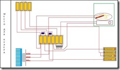
Here is the diagram to assemble:

Here is a visual diagram:

Now attach the transistor to the heatsink and the heatsink to the base.


The next step is to prepare the cooler. Remove the sticker, then the rubber plug on the back. Using a small screwdriver or tweezers, remove the cotter pin (circlip). Remove the blades.

You will see 4 coils attached to the chip with three legs. Grab the core of the coils with pliers and insert a small screwdriver into the space for the blade axle. Holding everything firmly by the core, hit the screwdriver with a hammer. The microcircuit with coils must separate from the entire structure.

Unsolder the coils from the microcircuit. The chip has 3 pins, you must insert a cutoff pin as the fourth pin. There are 2 wires soldered to one of the legs, unsolder one and solder it to the new leg so that there is one wire going to each leg.

Place the coil assembly back onto the axle, solder 4 different colored wires and lead them out.

It would seem that it would be easier to make a wind generator using a fan as a basis? However, several obstacles will stand in the way of such a technical transformation. This article will tell you how to overcome them, and what a wind power station made from a fan can be used for.
It’s worth making a reservation right away: you shouldn’t expect that the fruit of your labors will be a unit that can charge industrial batteries or heat buildings. Charging a mobile phone, or operating a small LED illuminator - approximately such tasks can be solved by a wind generator, which is, so to speak, a product of deep processing of a fan.
Why do such externally similar devices require effort to transform into each other? There are technical explanations for this that are worth considering.
The movement of electrons, an electric current, occurs in a conductor under the influence of a changing external magnetic field. Electric motors are designed similarly, only in the reverse order - a force acts on moving charged particles in a magnetic field, which forces the conductor to change its position in space, i.e. causes the rotor to move.
Both in generators and in engines, this same magnetic field is created in the stator or rotor, depending on the model, by permanent magnets or electromagnets (excitation windings). If the motor attracts iron objects, it is on permanent magnets. This option is optimal from the point of view of using it as a generator, since it does not require any modernization.
“Using a motor with excitation windings to generate electricity will be more difficult, because you will have to provide power to these same windings. And this will significantly complicate the design.”
This is how a car generator actually works. 12V is supplied to the rotor through the “tablet”, brushes and slip rings. The magnetic field it creates rotates along with the rotor. It is this that creates an electric current in the stator winding (of course, more current is generated than consumed, otherwise why would a generator be needed).
When the battery is fully charged and powerful consumers are turned off, almost no current is supplied to the rotor and the generator rotates idle. And using a self-generator as a wind power plant, this current will have to be supplied and its parameters controlled.
Sometimes it is proposed to remove the windings from the rotor in such a case and glue in neodymium permanent magnets instead of wire (in this case no current is needed), but this is a topic for a separate article.
Since the design of the fan meets the goal of pushing a mass of air, but, on the contrary, is driven by currents of air masses, the geometry will differ slightly. The angle of attack of the tips of the blades of both types differs little. 
The closer you move to the center, differences are observed.
Wind turbine propeller:
The section of the blade at the center practically does not participate in energy generation, since it moves many times slower than the entire blade, so it is made with an angle of attack equal to zero so that air masses can easily pass without creating congestion in the form of turbulence. A stationary fan does not need to change the angle of attack of the blade.
Since the overall geometry is similar, the fan propeller will also work as a wind generator.
It is unlikely that at least one fan, when exposed to wind, will produce the same speed as when plugged into the network. Therefore, you should not hope that a 100-watt wind generator made from a 12V fan will produce the same voltage and provide 100-watt operation to consumers.
Making such a wind generator is as easy as shelling pears. The toy uses an electric motor most often of 1.5 or 4.5 volts with independent excitation from permanent magnets. There is a ready-made screw. You need to take out the batteries, connect the wires to the + and − contacts, place the fan in the air flow, turn it on, and you can measure the characteristics of the generated current at the contacts.
In order for such a wind generator to work better, it would not hurt to add power to the propeller blades, for example, with linings cut from a plastic pipe in the shape of petals. Well, you will have to equip the unit with some other elements required for an electric windmill. 
The fan will have to be protected from precipitation with a special casing and mounted on a movable frame. The movable fastening of the frame to the mast must include a contact-brush mechanism (without it, the current cannot be transmitted down). The opposite end of the frame is equipped with a stabilizer; its task is to turn the wind generator towards the air flow.
What you can count on if the engine is 4.5V is 2.5...3V maximum, not even enough to charge a phone (usually 5V). But such a device, with sufficient wind, is quite capable of providing power to LEDs, which, for example, can be used to mark the boundaries of an entrance gate or illuminate the boundaries of a garden path.
This fan most often has a 12V motor, as in the previous example with permanent magnets, and its transformation into a wind generator occurs in the same order.
The differences are that:
The option is more complicated, but if the previous options were initially considered as toys, then this design can have quite tangible returns. The wind generator in question can serve, for example, to charge a 12V battery. The electricity stored in the battery, passed through a 12/220 converter, can be used as a home network.
The design uses a 24V fan motor. The blades are shortened, leaving only the fragments necessary for attaching new ones - cut from a PVC pipe (it will not be possible to use PVC bottles for these purposes - due to their low rigidity, they will simply be bent by the wind).
The blades are cut out approximately according to the same pattern as in the photo. 
The number of blades can be any; the most commonly used options are 3, 4 or 6.
The wind generator is assembled according to the classical scheme (Fig. 3). The voltage generated by it at a moderate 4...7 m/s will be more than 12V, which will allow charging the battery. A diode must be added to the electrical circuit so that if there is no wind, the power plant does not turn into a fan on the mast.
A battery charging controller, which regulates the charging current and opens the circuit when charging is complete, will also help. You can do without it, but then you will have to constantly monitor the charging process and adjust it manually.
Hello everybody! There are many circuits of high-voltage generators on the network that differ in power, assembly complexity, price and availability of components. This homemade product is assembled from almost waste parts; anyone can assemble it. This generator was assembled, let’s say, for informational purposes and all kinds of experiments with high voltage electricity. The approximate maximum of this generator is 20 kilovolts. Since this generator does not use mains voltage as a power source, this is an additional plus from a safety point of view.

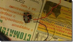
The photo shows all the necessary parts to assemble a high-voltage generator.
For assembly you will need:
Ignition coil from VAZ
Cooler with hall sensor
"N" channel mosfet
100 Ohm and 10 kOhm resistors
Connecting insulated wires
Soldering iron
Terminal block (optional)
Heatsink for mosfet
Several screws
Plywood base for fastening parts

If anyone is interested, I’ll try to tell you more. A computer cooling cooler or similar 12 volt is used as a pulse generator, but with one condition - it must have a built-in hall sensor. It is the hall sensor that will generate pulses for the high-voltage transformer, which, in this case, is the ignition coil from the car. Choosing a suitable fan is very simple; as a rule, it has three inputs.

The photo shows the presence of three conclusions. The standard color is red pin plus power, black – common (ground) and yellow – output from the hall sensor. When power is supplied to the fan at the output (yellow wire), we receive pulses, the frequency of which depends on the speed of the electric motor of a given cooler and the higher the voltage, the higher the frequency of the pulses. The voltage should be increased within reasonable limits - approximately 12-15 volts, so as not to burn the cooler and the entire circuit. The resulting pulse signal must be applied to the ignition coil, but it must be amplified.

As a power switch I used an “N” channel field-effect transistor (mosfet) IRFS640A; others with similar parameters are suitable, or approximately for a current of 5-10 amperes and a voltage of 50 volts for reliability. Mosfets are present in almost all modern electronic circuits, be it a computer motherboard or the starting circuit of an energy-saving lamp, which means that finding a suitable one will not be a problem.

The ignition coil from VAZ “classic” B117-A cars has three terminals. The central one is a high-voltage output, “B+” is positive 12 volts, and the general “K” is probably not marked.
Initially, the circuit consisted of three components: a cooler, a mosfet and a coil, but after a short time of operation it broke down, as either the mosfet or the hall sensor failed. The output is to install 100 Ohm resistors to limit the inrush current from the Hall sensor to the gate, and a 10 kOhm pull-up resistor to turn off the mosfet in the absence of a pulse.

When assembling the circuit, the transistor should be installed on a radiator, preferably using thermal paste, since the heating during operation is significant.

I used the connector from the cooler as a terminal block to connect the mosfet. As a result, there is no need to solder the transistor; to connect or replace it, it is enough to connect the block to the terminals of the transistor.

The fan was secured on top of the radiator using two self-tapping screws. As a result, it turned out that the cooler plays a dual role - as a pulse generator and as additional cooling.


