Smartphones that support Qi wireless charging are still a rarity. For some reason, most manufacturers ignore this technology, but in vain, because charging a device with a cable is not as convenient as without it. Cables wear out and you have to buy new ones from time to time, and you risk damaging the charging port if you accidentally jerk your smartphone. Devices with wireless charging do not have such problems.
Wireless charging can be added to any smartphone, and this can be done in several ways: purchase a special case or buy an inductor and install it inside the case.

Cases that support wireless charging are produced mainly for the most popular smartphone models. This is due to the fact that they are difficult to produce and are relatively expensive. It is most likely useless to look for them in local electronics stores, but there are a lot of them in online stores like AliExpress.

The first type is coils, which are equipped with special contacts and supply energy directly to the battery. They are only suitable for smartphones that have the corresponding contacts inside. Manufacturers of such devices sell wireless charging kits as additional accessories, but you can also purchase cheaper non-original analogues.

The second type is universal coils, which are installed either inside the smartphone or under the case and transmit energy to the charging port. Their obvious drawback is that the port is always busy, which means you won’t be able to charge your smartphone with a cable or connect it to your computer. When choosing a reel, it is important to pay attention to the orientation of the USB connector and the length of the cable. You can see whether this or that coil is suitable for your smartphone on the product description page in the online store. If in doubt, consult the seller - he will select the appropriate option.
Keep in mind that smartphones tend to charge slower with wireless charging than with a cable. This is due to losses during the transfer of energy from one coil to another.
Wireless charging bases are sold in stores and online; they support Qi technology and are universal. When choosing a base, you should be guided by your taste, and also look at the maximum power. The larger it is, the better, but within reasonable limits - 10 watts is quite enough, but the output will still be about half as much. You should not take a base that is too powerful, as it can cause the battery to overheat. Some sellers sell kits consisting of a charging base and a receiver coil.
After purchasing a wireless charging kit, disassemble the smartphone, connect the receiver coil to the contacts or charging port, and the base to the USB network adapter and place the smartphone on the base. A charging indicator should appear on the base (usually a green LED lights up, but there may be other options), and the battery indicator on the smartphone will show that the device is receiving power. In the case of charging cases, it’s even easier; you don’t need to disassemble the smartphone and connect the receiver to the contacts.
Smartphone manufacturers compete with each other, equipping each new model with some unique feature. This is how phones with the function became available to users. Convenient, fast, it promises maximum comfort when working with the gadget. But, as a rule, it does not come with a smartphone. The cost of the cheapest model starts from 700 rubles, a more or less normal one will cost 2.5 thousand rubles. And of course, the user has a logical question: how to make wireless charging with your own hands? It turns out that if you want and have some details, this is quite simple to do, but first you need to familiarize yourself with all the accompanying nuances.
A wireless charger allows you to charge your phone without connecting it to wires. The mobile phone is placed on a special stand, where the whole process takes place.
The operating principle is to transmit a magnetic field from the transmitter to the receiver. The second one in this case begins to generate voltage, which charges the battery.
The presence of a built-in receiver can be seen in the specifications; if the manufacturer indicated support for the Qi standard, then everything is in order.

ATTENTION. The lack of a built-in receiver in a gadget is not a reason to abandon the idea. In this case, the smartphone owner simply needs to put in a little more effort and make the receiver himself.
There are several options for performing the work, the essence of which ultimately comes down to one thing. If you place all the elements on a clean board, attach them with a soldering iron and equip the structure with a choke, you can get a high-quality device. It will be capable of delivering voltage up to two amperes, operating reliably and uninterruptedly. However, if you have a minimum of materials at hand, it is worth using a simpler scheme. To choose the most suitable option, it is worth considering both.
Before making a reliable and high-quality wireless charger with your own hands, you need to prepare:
First of all, a circuit is made from a long wire. To do this, the wire is folded in half, using fingers or a contour with a diameter of 5–10 centimeters, 5 turns are wound. Along the entire circumference, the contour is firmly fastened with tape or glue.

Next, you need to cut the loop resulting from folding the wire in half, you get 4 free ends. They are cleaned, the beginning of the first winding is connected to the end of the second, and the end of the first winding is connected to the beginning of the second. A multimeter will help you determine which end should connect to which. The “active” ends are soldered together, forming a midpoint. It is she who will go to the plus of the power supply through the inductor. Resistors will later be connected to the free ends.
Assemble for a phone with your own hands in the following sequence: solder two transistors, then diodes to them, and resistors to the diodes, in turn. The ends of the latter are distributed between the board and diodes. The circuit is soldered last, and both windings are pre-tinning.
A do-it-yourself smartphone transmitter assembled in this way creates a high-frequency field on the primary circuit, which is smoothed out by a capacitor on the secondary circuit and stabilizes to approximately 5 volts.
The second option will tell you how to make wireless charging for your phone in a simpler way using a minimum of materials. You will need:
The wire is wound in forty turns per frame. It must be prepared in advance, based on the optimal diameter of 7–10 centimeters. After the twentieth turn, layering is done. A resistor is connected to it and the end of the coil, at which point the device is considered ready.

ADVICE. It is worth considering the conductivity of the resistor; if it is direct, the polarity must be changed during assembly.
The transmitter should be placed in a housing; a disc box is perfect for its role.
If the smartphone is not equipped with a built-in receiver, then you will need to spend time making one. You can install your receiver not only on a smartphone, but also on a regular push-button one, since it is connected to a battery.
Do-it-yourself wireless charging for a smartphone in this case will require a wire with a diameter of 0.3–0.4 mm. Double-sided tape and superglue will also come in handy. For convenience, work on creating the contour can be done on a plastic surface.

The receiver consists of 25 turns, pressed tightly together. To prevent the structure from breaking in the future, it is recommended to fasten the coils with double-sided tape and, as the area increases, fill them with superglue.
In addition to the wire, the receiver includes a silicon diode, the marking of which does not make much difference. The turns of the second part are carefully separated from the surface and connected to the device through a diode.

In addition to how to make wireless charging, it is worth thinking about how to connect it. The receiver can be connected either to the battery or to the charger connector. The second option, as practice shows, is more preferable.
All that remains is to attach the made receiver to the cover of the smartphone and you can start testing.
IMPORTANT. To check the functionality of the wireless charger, you should take an old phone, the loss of which due to errors in the assembly will not cause damage to the owner. It is also not recommended to charge a phone that is under manufacturer’s warranty in this way.
Before you learn how to make wireless charging yourself, you should know the following:
Sometimes the chargers used by gadgets fail. There are people who are interested in trying everything themselves. As a result, homemade phone chargers are born.
How to charge your phone? This question does not concern many people, but only until they are faced with problems that can lie in wait for everyone.
So, why might we need to create a phone charger?
The easiest way to resolve the question is how to make a portable phone charger using batteries.
How to charge a phone if you have batteries, a compartment for them, for them or an old mobile phone and a USB extension cord?
Batteries must be AA type. In addition, a soldering iron and tester should be available.
We take 4 batteries (preferably large capacity) and insert them into the battery compartment. We measure the voltage with a tester, it should be at least 5 volts. This is due to the fact that modern phones can be charged from a USB connector, in which the voltage is 5 V.
From a USB extension cable that you don’t mind using, cut off the plug that connects to the computer. We study the pinout of the contacts, call the tester. We find + and -, remove the remaining wires with wire cutters and insulate them.

We put a thermal casing on the wires and treat it with a lighter to ensure a tight entry. We try on the place where the plug is attached.
We will need to solder the wires to the metal rivets. For this purpose, soldering acid is used, which can be applied with a tin stick, after which we tin the rivets.
We solder the wires according to their charge.
The connector must be glued to the body, having first degreased or scraped off the connector and plastic with a knife.
Apply heated glue to the body and press. Apply glue around it, closing the open contacts. The remaining unnecessary wires are bitten off and covered with glue. If necessary, it can be masked using a marker.
We insert the batteries. They must be of the same capacity. Moreover, their total capacity must exceed that of a telephone battery.

After making the charger itself, the question “How to make a charger for your phone?” cannot be removed because the cable still needs to be made.
We cut off the small connector of the USB cable; the length of the cable should be half a meter.
We cut the wires in the same way. + and - have already been identified, there is no need to repeat them. We bite off the remaining wires, then place them in a thermal casing, strip them, and tin them.
Batteries can be charged in different places intended for them. In most cases, you can also use cell phone chargers.
You don’t have to complicate your life and charge your batteries in appropriate chargers.

We insert the charged batteries into the booster, to which we connect the USB cable on one side, and connect it to the phone with the other side and check the charging.
After some time, the voltage on the booster may drop, so it is better to use batteries with a larger capacity.
Thus, we figured out how to make a phone charger with your own hands.
Extension cords may stop charging the phone, they may become frayed, and the charging socket on the phone may become loose. All this necessitates wireless charging. Let's look at how to make wireless charging for your phone below.
The principle of wireless charging is based on the fact that a coil is built into the charger, which creates a magnetic field; under the cover of the phone there is another coil that serves as a receiver. When the receiver is in range of the conductor, electromagnetic pulses are activated. The phone battery is affected through rectifiers and capacitors.
But before you make your choice in favor of wireless charging, you need to consider that it has a number of negative qualities:

Let's figure out how to make wireless charging for your phone.
To do this, you need several meters of thin copper wire. We wind the conductor into a coil with a number of turns equal to 15. To maintain the shape, secure the spiral with double-sided tape or glue. Leave a few centimeters of wire for soldering. The connection to the charging socket is made using a capacitor and a pulse diode, which are attached to opposite ends.
The size of one turn on the conductor should be 1.5 cm. After twisting, the diameter of the resulting coil is 10 cm.
To form the transmitter, an even thinner copper wire of 30 turns is used. The circuit is closed by a capacitor and a transistor. We place this device in the area of the transmitting ring with the display facing up.
Thus, the question of how to charge your phone has several answers. Charging can be portable from batteries, or it can be wireless. In any case, it should be done by a person who understands electricity, otherwise you may run into problems.
This device was conceived a long time ago and was tested several times; everything presented below is the author’s development. Despite the very simple circuit, the device operates very stably. The device itself is a charger for a mobile phone without using wires.
How does all this work?
This device was published on this site. The first version turned out to be not very effective, then other versions were invented. This option turned out to be the most economical. The device allows you to charge your phone if the latter is located at a distance of no more than 3 - 4 cm from the receiver. The basis of the first device is a highly efficient PWM controller that can generate rectangular pulses with a frequency of up to 1 MHz, but due to large losses the idea turned out to be not very good, although this device allowed mobile devices to be charged at a distance of up to 50 cm from the receiver.
After some unsuccessful attempts to create such a device, a simplified blocking generator came to the rescue, which I successfully used in electroshock devices.
The main advantages of the device:
1) Low consumption
2) High efficiency (compared to its counterparts)
3) Relatively high charging current
4) Ability to operate from a reduced source (the first version operated from a voltage of 9-16 volts)
5) Simplicity and compactness
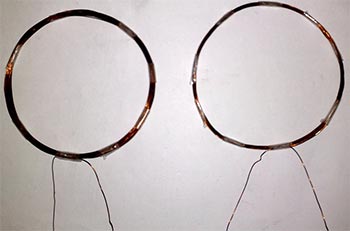
The transmitting part of the device consists of two main circuits. Each of them has a diameter of 10 cm, wound with 0.8 mm wire. The first circuit (L1) consists of 20 turns, the second of 35 turns of the same wire. The contours are laid on top of each other and decorated with adhesive tape or insulating tape.
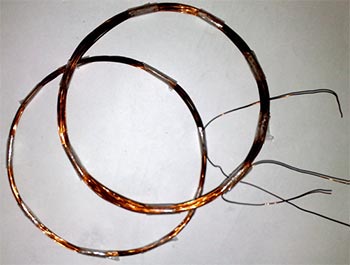
It is necessary to number the coil terminals in advance, since they need to be phased. They do phasing like this - the beginning of the first coil is connected to the end of the second or vice versa, the main thing is to get one coil with a tap.

Next, we select the resistance (if you plan to start the device from a reduced source, then the resistor can be removed).
It is advisable to use a trimming resistor of 0...470 Ohm; the power of the resistor is not very important (0.25-2 Watt).

How to setup? Just! First, let's assemble the receiver circuit. We connect the power (any stabilized constant voltage source 4.5-9 volts). We adjust the resistor so that the quiescent current of the circuit does not exceed 150mA.
The maximum current consumption of the circuit is no more than 600mA, you will agree that this is not much.
After selecting the optimal resistance, you can replace the variable with a constant resistor (0.25-1W). The resistance of the basic limiter directly depends on the input voltage rating.
In my version, the transistor did not overheat, but just in case, install it on a small heat sink.
The device starts operating from a voltage of 1 volt - another feature of this design, but at this voltage it will not charge a mobile phone; instead, it can be used as a converter to power low-power devices.
Transistor - you can use literally any low-frequency transistor, regardless of structure. The circuit uses a KT818 transistor, which can be successfully replaced with 837, 816, 814 or 819, 805, 817, 815, only when using reverse conduction transistors, the power polarity should be changed.
The design of the receiver is outrageously simple - a circuit, a rectifier, a zener diode and a storage capacitor. A pulse diode is needed, preferably in an SMD version, since the entire circuit will be located in a mobile phone. In my case, a fairly powerful and common Schottky diode SS14 was used. Such a diode is capable of operating at frequencies up to 1 MHz, the current is up to 1A!

The capacitor is not critical; it has a capacity from 47 to 220 µF (more is of course better, but there may not be enough space). Capacitor voltage is from 10 to 25 Volts.
Zener diode - any voltage of 5-6 volts (often found with a voltage of 5.6 Volts, for example - BZX84C5V6).

The receiver circuit (L3) contains 15 turns of 0.3-0.7 mm wire, wound in a spiral on the outer or inner side of the back cover of the phone.
The circuit can be assembled on a compact board or placed in a convenient place using hinged mounting, but it is advisable to fill the mounting with rubber glue or silicone.

A Sony Ericsson K750 was used as a test phone; it was fully working and was purchased specifically for these experiments (bought with spare parts for $5), then a handy Nokia N95 was converted.
The device can charge a mobile phone quite quickly, it all depends on the total power, in this case a 1000mA battery is fully charged in 3 hours.
The current is transmitted to the second circuit by electromagnetic induction, in this case it is completely safe, since the frequency is reduced, there are no harmful effects on humans.
In order to install the receiving circuit, the mobile phone is disassembled. An industrial charger is connected to the charging socket and the polarity is found on the socket contacts. Next, the receiver pins are connected to the corresponding pins of the socket.

The outline can be attached to the back cover of the phone using epoxy resin, silicone (highly not recommended), super glue (use only when the outline is planned to be attached to the outside of the cover).
| Designation | Type | Denomination | Quantity | Note | Shop | My notepad |
|---|---|---|---|---|---|---|
| VT1 | Bipolar transistor | KT818A | 1 | KT837, KT816, KT814 | To notepad | |
| VD1 | Zener diode | BZX84C5V6 | 1 | 5-6 Volt | To notepad | |
| VD2 | Schottky diode | SS14 | 1 | To notepad | ||
| C1 | Electrolytic capacitor | 10 µF | 1 |


