Let us immediately note that the word “inexpensive” means coupes that are more or less common on Russian roads, with a price that still differs from the astronomical price! More precisely, cheaper than three million rubles, in order to avoid paying luxury tax.
In addition, buyers often confuse the coupe with three-door hatchbacks like the Opel Astra GTC and Renault Megane Coupe. But manufacturers, for marketing and advertising reasons, do not correct this mistake.
Our review presents true coupes, that is, two-door sedans. Those whose trunk lid opens without a rear window.
However, when compiling the list, we, unfortunately, were not able to fully comply with the status quo.
Some models are so skillfully camouflaged, and in their lack of pragmatism they are so similar to a coupe, that we could not help but include them in the review, albeit with some reservations.
Cost – from 799,900 rubles
Actually, the most inexpensive coupe on the Russian market. Therefore, you shouldn’t demand much from the car, especially in terms of driving characteristics. In fact, this is an ordinary Kia Sid, covered with a less practical, but more show-off body, which is what attracts the car in the first place. Another vote in favor is the presence of a two-liter engine in the base and a good list of included options.
Cost – from 888,000 rubles

The smallest “coupe” on the Russian market. Mini is another car that is not formally classified as a coupe, being a three-door hatch. And in terms of driving qualities - in general, cards, and in the best sense of the word! But a very specific appearance with a cut-out roof at the rear of the body and a strictly two-seater interior still makes it possible to separate the MINI Coupe from its more familiar brother.
Cost – from 1,069,000 rubles

A car with an amazing production history. The concept shown at the Frankfurt Motor Show was so warmly received by the public that the French decided to put the experimental car into production virtually unchanged. In every sense, a very interesting and driver-friendly car is selling with a bang in Europe, but in Russia it is selling very poorly, despite the initially attractive price. It’s not so much the presence of only two versions with a capacity of 160 and 200 horsepower, but rather the extremely biased attitude of Russians towards French cars. And unfortunately, due to extremely low demand, the charismatic coupe will soon leave the Russian market.
Cost of Toyota GT86 – from 1,294,000 rubles

There is no point in separating these cars. The BRZ and GT86 are the same car, created by a joint Japanese effort during a period of general cost savings. But the car is very successful. The rear-wheel drive coupe turned out to be truly sporty and exciting. For the experienced driver!
Cost of Subaru BRZ – from 1,436,000 rubles

The coupes are separated from the market solely financially. Subaru, which considers itself a premium brand, only sells the BRZ in one top-end trim. Toyota has three modifications with two gearboxes. There is one engine for two – a two-liter 200-horsepower boxer engine.
Cost of BMW 2-series – from 1,331,000 rubles

According to the new ideology of the brand, BMW brought coupes and convertibles into a separate even-numbered series. So the ideological follower of the “penny coupe” is now called the BMW 2-series. In fact, the car is unique for the Russian market - the only rear-wheel drive model in the golf class. Possessing excellent driving qualities and a “hooligan” character, the BMW 2-series is offered in three modifications: with gasoline or diesel two-liter engines with a capacity of 184 horsepower each, and in the top-end M235i version with 326 horses.
Cost of BMW 4-series – from 1,750,000 rubles

The “older” BMW 4-series, despite the innate driver’s “vein”, has already been made with a great eye on comfort. We still need to select clients from our main rivals with the three-pointed star! The range contains the same engines as the “two”, except that the most powerful one no longer has the “M” designation.
Cost – from 1,499,000 rubles.

Unfortunately, another car that is “dying out” in our market due to its origin. Russia is not yet ready to buy “French” ones at a price of one and a half million rubles. Dealers are selling their last remaining stock. Anyone who decides to buy will receive a very unusual outside, stylistically ascetic inside, but in any case a calm and comfortable car with a single 2-liter gasoline engine with 170 horsepower.
Cost – from 1,599,000 rubles

The strategic task of the Koreans is to fill all existing niches by any means. Hyundai's lineup should have everything, including, of course, a coupe. Genesis is a car for those who need maximum... show-off for minimal money. Spectacular appearance, powerful 250-horsepower engine, 8-speed automatic transmission, rear-wheel drive and maximum equipment. Cool? Cool! Only the driving characteristics, which are average for such a car in the absence of a pretentious logo, force buyers to look in other directions.
Cost of Mercedes-Benz C-coupe – from 1,620,000 rubles

Like BMW, the Stuttgart people also honor true traditions and maintain their brand by offering the buyer traditional rear-wheel drive coupes. The most inexpensive of them is the C-coupe. The two-door “tseshka” has a range of three gasoline engines with power from 156 to 306 horsepower and, of course, a hyperversion with a 457-horsepower engine from the AMG studio!
Cost of Mercedes-Benz E-coupe – from 1,995,000 rubles

Mercedes, of course, also has a larger and more thoroughbred coupe, designated by the letter “E”. Oddly enough, the car is indirectly related to the E-class sedan, since technically the model is built on the basis of the same C-class. What Mercedes doesn’t really advertise, and buyers aren’t particularly interested in it – it says E-class, which means E-class! In the end, any Mercedes is good, especially when he is handsome and strong. Under the hood of the “yeshka-kupeshka” there can be one of four engines with a capacity of 184 to 306 horsepower.
Cost of Audi A5 – from 1,630,000 rubles

In the model range of this German manufacturer, there is essentially only one classic coupe - the A5 model. The attractively shaped car has a range of four engines and (according to Audi tradition) two sports modifications: S5 and RS5. And the only drawback of the car is its age - the model has been in production for the eighth year (!), periodically undergoing modernization.
Cost of Audi TT – from 1,643,000 rubles

Even older is the Audi TT, which we also conditionally classify as a coupe, although in fact the car does not belong to this class. But the TT is really not much different from a coupe in its appearance and driving capabilities. Today, the car has lost the image of an “alien saucer”, and behind it, its former popularity. The range includes four engines with power from 160 to 340 horsepower.
They are polar and non-polar. Their differences are that some are used in DC voltage circuits, while others are used in AC circuits. It is possible to use permanent capacitors in alternating voltage circuits when they are connected in series with like poles, but they do not show the best parameters.
Non-polar, just like resistors, can be fixed, variable or adjustable.
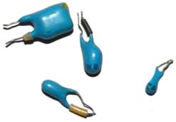
Trimmers capacitors are used to tune resonant circuits in transmitting and receiving equipment.
Rice. 1. PDA capacitors
PDA type. They consist of silver-plated plates and a ceramic insulator. They have a capacity of several tens of picofarads. It can be found in any receivers, radios and television modulators. Trimmer capacitors are also designated by the letters KT. Then follows a number indicating the type of dielectric:
1 - vacuum; 2 - air; 3 - gas-filled; 4 - solid dielectric; 5 - liquid dielectric. For example, the designation KP2 means a variable capacitor with an air dielectric, and the designation KT4 means a tuning capacitor with a solid dielectric.
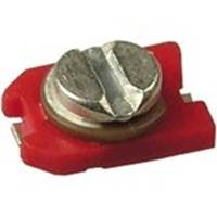
Rice. 2 Modern trimming chip capacitors
To tune radio receivers to the desired frequency, use variable capacitors(KPE)

Rice. 3 Capacitors KPE
They can only be found in transmitting and receiving equipment
1- KPE with an air dielectric, can be found in any radio receiver of the 60s-80s.
2 - variable capacitor for VHF units with vernier
3 - variable capacitor, used in receiving technology of the 90s to this day, can be found in any music center, tape recorder, cassette player with a receiver. Mostly made in China.
There are a great many types of permanent capacitors; within the framework of this article it is impossible to describe all their diversity; I will only describe those that are most often found in household equipment.

Rice. 4 KSO capacitor
KSO capacitors - Pressed mica capacitor. Dielectric - mica, plates - aluminum coating. Filled in a brown compound housing. They are found in equipment from the 30s to the 70s, the capacity does not exceed several tens of nanofarads, and is indicated on the housing in picofarads, nanofarads and microfarads. Thanks to the use of mica as a dielectric, these capacitors are capable of operating at high frequencies, since they have low losses and have a high leakage resistance of about 10^10 Ohms.
Rice. 5 Capacitors KTK
KTK capacitors - Tubular ceramic capacitor. A ceramic tube and silver plating are used as a dielectric. Widely used in oscillatory circuits of lamp equipment from the 40s to the early eighties. The color of the capacitor indicates TKE (temperature coefficient of change of capacitance). Next to the container, as a rule, the TKE group is written, which has an alphabetic or numerical designation (Table 1.) As can be seen from the table, the most heat-stable ones are blue and gray. In general, this type is very good for HF equipment.
Table 1. TKE marking of ceramic capacitors

When setting up receivers, you often have to select capacitors for the local dyne and input circuits. If the receiver uses KTK capacitors, then selecting the capacitance of the capacitors in these circuits can be simplified. To do this, several turns of PEL 0.3 wire are wound tightly onto the capacitor body next to the terminal and one of the ends of this spiral is soldered to the terminal of the capacitors. By spreading and shifting the turns of the spiral, you can adjust the capacitance of the capacitor within small limits. It may happen that by connecting the end of the spiral to one of the terminals of the capacitor, it is not possible to achieve a change in capacitance. In this case, the spiral should be soldered to another terminal.


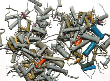
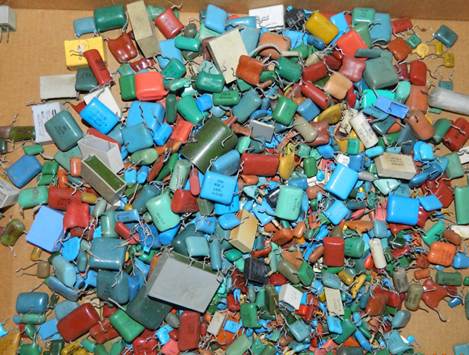
Rice. 6 Ceramic capacitors. Soviet ones at the top, imported ones at the bottom.
Ceramic capacitors are usually called “red flag” capacitors, sometimes called “clay” capacitors. These capacitors are widely used in high frequency circuits. Typically, these capacitors are not quoted and are rarely used by hobbyists, since capacitors of the same type can be made of different ceramics and have different characteristics. Ceramic capacitors gain in size but lose in thermal stability and linearity. Capacity and TKE are indicated on the body (Table 2.)
table 2
Just look at the permissible change in capacitance for capacitors with TKE N90, the capacitance can change almost twice! For many purposes this is not acceptable, but still you should not reject this type; with a small temperature difference and not strict requirements, they can be used. By using parallel connection of capacitors with different TKE signs, it is possible to obtain a fairly high stability of the resulting capacitance. You can find them in any equipment; the Chinese are especially fond of them in their crafts.
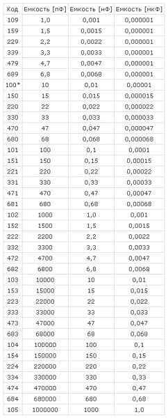
They have a capacity designation on the body in picofarads or nanofarads; imported ones are marked with a numerical code. The first two digits indicate the capacitance value in picofarads (pF), the last two digits indicate the number of zeros. When the capacitor has a capacitance of less than 10 pF, the last digit may be "9". For capacitances less than 1.0 pF, the first digit is “0”. The letter R is used as a decimal point. For example, code 010 is 1.0 pF, code 0R5 is 0.5 pF. Several examples are collected in the table:
Alphanumeric marking:
22p-22 picofarads
2n2- 2.2 nanofarads
n10 - 100 picofarads
I would like to especially note ceramic capacitors of the KM type, they are used in industrial equipment and military devices, they have high stability, they are very difficult to find because they contain rare earth metals, and if you find a board where this type of capacitor is used, then in 70% of cases they were cut out before you).
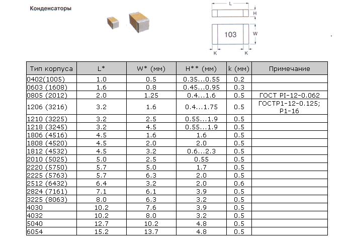
In the last decade, radio components for surface mounting have very often begun to be used; here are the main standard sizes of housings for ceramic chip capacitors
MBM capacitors are a metal-paper capacitor (Fig. 6), usually used in tube sound amplification equipment. Now highly prized by some audiophiles. This type also includes military-grade K42U-2 capacitors, but they can sometimes be found in household equipment.
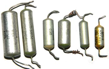
Rice. 7 Capacitor MBM and K42U-2
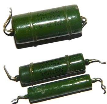
It should be noted separately that such types of capacitors as MBGO and MBGCh (Fig. 8), are often used by amateurs as starting capacitors to start electric motors. As an example, my engine reserve is 7 kW (Fig. 9.). Designed for high voltage from 160 to 1000V, which gives them many different applications in everyday life and industry. It should be remembered that for use in a home network, you need to take capacitors with an operating voltage of at least 350V. You can find such capacitors in old household washing machines, various devices with electric motors and in industrial installations. They are often used as filters for acoustic systems, having good parameters for this.
Rice. 8. MBGO, MBGCH

Rice. 9
In addition to the designation indicating design features (KSO - compressed mica capacitor, KTK - ceramic tubular capacitor, etc.), there is a designation system for constant-capacity capacitors, consisting of a number of elements: in the first place is the letter K, in the second place is a two-digit number, the first digit of which characterizes the type of dielectric, and the second - the features of the dielectric or operation, then the serial number of the development is put through a hyphen.
For example, the designation K73-17 means a polyethylene-terephthalate film capacitor with a development serial number of 17.
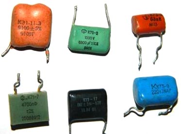
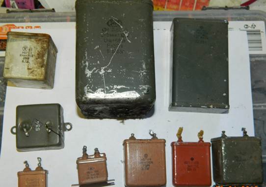
Rice. 10. Different types of capacitors

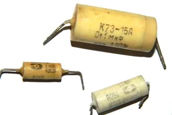
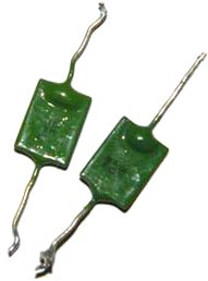
Rice. 11. Capacitor type K73-15
Main types of capacitors, imported analogues in parentheses.
K10 - Ceramic, low voltage (Upa6<1600B)
K50 - Electrolytic, foil, Aluminum
K15 - Ceramic, high voltage (Upa6>1600V)
K51 - Electrolytic, foil, tantalum, niobium, etc.
K20 - Quartz
K52 - Electrolytic, volumetric porous
K21 -Glass
K53 - Oxide semiconductor
K22 - Glass-ceramic
K54 - Oxide-metallic
K23 - Glass enamel
K60- With air dielectric
K31-Mica low power (Mica)
K61 - Vacuum
K32 - Mica high power
K71 - Film polystyrene (KS or FKS)
K40 - Paper low-voltage (Irab<2 kB) с фольговыми обкладками
K72 -Film fluoroplastic (TFT)
K73 - Film polyethylene tereph-talate (KT, TFM, TFF or FKT)
K41 - Paper high-voltage (irab>2 kB) with foil coverings
K75 -Film combined
K76 – Lacquer film (MKL)
K42 - Paper with metallized covers (MP)
K77 - Film, Polycarbonate (KC, MKC or FKC)
K78 – Film polypropylene (KP, MKP or FKP)
Capacitors with a film dielectric are popularly called mica; the various dielectrics used give good TKE indicators. As plates in film capacitors, either aluminum foil or thin layers of aluminum or zinc deposited on a dielectric film are used. They have fairly stable parameters and are used for any purpose (not for all types). They are found everywhere in household equipment. The housing of such capacitors can be either metal or plastic and have a cylindrical or rectangular shape (Fig. 10.) Imported mica capacitors (Fig. 12)

Rice. 12. Imported mica capacitors
On capacitors, the nominal deviation from the capacitance is indicated, which can be shown as a percentage or have a letter code. Basically, in household equipment, capacitors with tolerances H, M, J, K are widely used. The letter indicating the tolerance is indicated after the value of the nominal capacitance of the capacitor, like 22nK, 220nM, 470nJ.
Table for deciphering the conditional letter code of the permissible deviation of capacitor capacitance. Tolerance in %
|
Letter designation |
||
The value of the permissible operating voltage of the capacitor is important; it is indicated after the rated capacity and tolerance. It is designated in volts with the letter B (old marking) and V (new marking). For example, like this: 250V, 400V, 1600V, 200V. In some cases, the V is omitted.
Sometimes Latin letter coding is used. To decipher, you should use the letter coding table for the operating voltage of capacitors.
|
Rated voltage, V |
Designation letter |
Fans of Nikola Tesla have a frequent need for high-voltage capacitors, here are some that can be found, mainly in televisions in horizontal scanning units.

Rice. 13. High voltage capacitors
Polar capacitors include all electrolytic ones, which are:
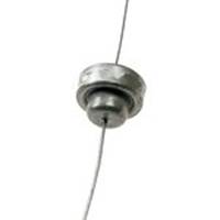
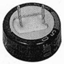
Aluminum electrolytic capacitors have high capacity, low cost and availability. Such capacitors are widely used in radio instrument making, but have a significant drawback. Over time, the electrolyte inside the capacitor dries out and they lose capacity. Along with the capacitance, the equivalent series resistance increases and such capacitors no longer cope with the assigned tasks. This usually causes malfunctions in many household appliances. Using used capacitors is not advisable, but still, if you want to use them, you need to carefully measure the capacitance and esr, so that you don’t have to look for the reason for the device’s inoperability. I don’t see any point in listing the types of aluminum capacitors, since there are no special differences in them, except for geometric parameters. Capacitors can be radial (with leads from one end of the cylinder) and axial (with leads from opposite ends), there are capacitors with one lead, the second one is a housing with a threaded tip (it is also a fastener), such capacitors can be found in old tube radio-television equipment. It is also worth noting that on computer motherboards and in switching power supplies there are often capacitors with low equivalent resistance, the so-called LOW ESR, so they have improved parameters and are replaced only with similar ones, otherwise there will be an explosion when first turned on.
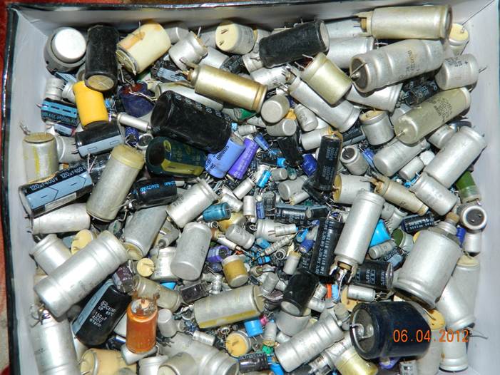

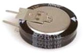
Rice. 14. Electrolytic capacitors. Bottom - for surface mounting.
Tantalum capacitors are better than aluminum capacitors due to the use of more expensive technology. They use a dry electrolyte, so they are not prone to “drying out” of aluminum capacitors. In addition, tantalum capacitors have lower active resistance at high frequencies (100 kHz), which is important when used in switching power supplies. The disadvantage of tantalum capacitors is the relatively large decrease in capacitance with increasing frequency and increased sensitivity to polarity reversal and overloads. Unfortunately, this type of capacitor is characterized by low capacitance values (usually no more than 100 µF). High sensitivity to voltage forces developers to increase the voltage margin by two or more times.

Rice. 14. Tantalum capacitors. The first three are domestic, the penultimate one is imported, the last one is imported for surface mounting.
Main dimensions of tantalum chip capacitors: 
One of the types of capacitors (in fact, these are semiconductors and have little in common with ordinary capacitors, but it still makes sense to mention them) include varicaps. This is a special type of diode capacitor that changes its capacitance depending on the applied voltage. They are used as elements with electrically controlled capacitance in circuits for tuning the frequency of an oscillatory circuit, dividing and multiplying frequencies, frequency modulation, controlled phase shifters, etc.


Rice. 15 Varicaps kv106b, kv102
Also very interesting are “supercapacitors” or ionistors. Although small in size, they have enormous capacity and are often used to power memory chips, and sometimes they replace electrochemical batteries. Ionistors can also work in a buffer with batteries in order to protect them from sudden surges in load current: at low load current, the battery recharges the supercapacitor, and if the current increases sharply, the ionistor will release the stored energy, thereby reducing the load on the battery. With this use case, it is placed either directly next to the battery or inside its housing. They can be found in laptops as a battery for CMOS.
The disadvantages include:
Energy density is lower than that of batteries (5-12 Wh/kg at 200 Wh/kg for lithium-ion batteries).
The voltage depends on the state of charge.
Possibility of internal contacts burning out during a short circuit.
High internal resistance compared to traditional capacitors (10...100 Ohm for a 1 F × 5.5 V ionistor).
Significantly greater self-discharge compared to batteries: about 1 µA for a 2 F × 2.5 V ionistor.

Rice. 16. Ionistors
IF YOU DON'T HAVE KPE
What can replace it?
If you did not have the opportunity to purchase a variable capacitor to assemble the receiver, how can you do without it?
The simplest option is to make a receiver with a fixed setting for one to three radio stations and use a switch for the corresponding number of positions. To configure the input circuit in this case, you will have to select the capacitor capacities to receive a certain number of radio stations. First, the capacitance of the capacitor is selected to tune the input circuit of the receiver to the highest frequency radio station. Then you can add the required number of others in parallel to the first capacitor to tune to longer wavelength radio stations.
For example: we want to make a radio receiver to receive two radio stations in the DV and SV bands. First, we wind a coil to receive a radio station in the CB range (about 70-90 turns on a ferrite rod). Next, install a capacitor with a capacity of approximately 200 pF into the circuit circuit. By moving the coil along the rod we try to catch the radio station we need. If this fails, we take a capacitor of a different capacity - 150 or 220 pF and again try to find the radio station we need. Of course, this process is very painstaking, so it is better to first make a simple high-frequency generator for setup:
The generator is a symmetrical multivibrator capacitively coupled to an oscillatory circuit. The multivibrator generates low-frequency rectangular oscillations with a frequency of about 1 kilohertz. Through capacitor C3, oscillations are supplied to circuit C4 L1. In this case, damped high-frequency oscillations arise in the circuit with the modulation frequency of the multivibrator. These pulses are large and can be picked up by the magnetic antenna of a radio receiver located near the generator.
The circuit coil is wound on a ferrite rod and contains 70 turns, PEV-0.15 wires. With this coil, the generator will cover the mid-wave range. For the long-wave range, the coil should contain about 200 turns of the same wire, wound in 5 sections. The loop capacitor is used with the air dielectric from large radios. A “beak” type handle is mounted on the condenser axis, under which there is a scale graduated in meters.
Generator coils are replaceable. In order to make it convenient to change them, you need to provide some kind of connector.
The generator is calibrated using any industrial radio receiver that has the appropriate range. It would be better if it was a portable transistor receiver. To calibrate the generator, you need to place its coil near the receiver body. First you need to set the receiver pointer to the longest wavelength section of the selected range. By slowly rotating the generator KPI knob, we achieve the appearance of a low-frequency signal from the generator in the receiver speaker. We make a mark on the generator scale opposite the “beak” of the handle. Next, set the receiver scale arrow to the next mark and again achieve the appearance of sound in the receiver speaker. This is how the entire scale of the generator is calibrated. It may happen that in some position of the generator handle the receiver receives a signal regardless of the receiver settings. This means that the generator is tuned to the intermediate frequency of the receiver (usually 465 Kilohertz). It is also useful to make a mark on the generator scale here. Later, when you build superheterodyne receivers, this signal can be very useful for tuning them.
If you remove the coil from the circuit and connect conductors to sockets 1 and 2, then this circuit can be used to test audio amplifiers.
Also, instead of KPE, you can successfully use a zener diode:

The operating principle of the circuit is that a silicon zener diode, when voltage is applied to it, changes its own junction capacitance in a fairly wide range.
The resistor value in this circuit can be from 100 Kom to 1 Mohm. The capacitance of capacitor C1 can be from 1 to 10 microfarads. Capacitor C2 prevents the DC voltage from closing. Its capacity can be from 2200 to 10000 pf.
The disadvantages of this circuit include the need to use a high supply voltage and a slight overlap of the receiving frequency. Also, when changing a zener diode, it is necessary to adjust the circuit to the operating frequency range (the capacitance value of different types of zener diodes can vary greatly).
For electronic frequency tuning of radio receivers, special diodes - varicaps - are used. There are varicaps for use in high-frequency ranges (every modern TV has several of them) and for low-frequency ranges (used in some radios). The varicap connection circuit is similar to the zener diode connection circuit given above.
A selection of articles from Radio magazines on making homemade variable capacitors is located.
To tune an oscillatory circuit wound on a ferrite core, you can use... an ordinary magnet! As is known, a ferrite core has a certain magnetic permeability. When the core is magnetized, its permeability changes over a fairly wide range. This property of cores is usually negative (you have to reduce the current through the coil), but it can also be used for good! You can read an article from Radio magazine on this topic.I continue to slowly deal with old military parts. This time - about coils and KPIs, since for me this is a very “painful” issue.
Reels.
The circuits of the inverter are quite large in size, in a hermetically sealed casing, with glass-covered leads. Resistors and capacitors of the anode and grid circuits are installed inside. The magnitude of the connection is adjusted using a movable flap, which changes the size of the gap in the partition. The date on the parts is 1954. The workmanship is impressive. I figured the frequency is about 12 MHz.
The following IF circuits are no less interesting. Also a sealed copper case with glass-covered leads. The details show 1975. Most likely used in an AM receiver.
In the photo: contours inside.
No less interesting contours of the inverter: round housing, for wall-mounted installation. The screen is screwed onto the base; a groove is made in the base, into which a round rubber seal is inserted. Inside the screen there is a plastic insulating glass. I liked these circuits the most, since they are best suited for practical use in VHF receivers and there are enough of them for this.
In the photo: round contours of the frequency converter.
There are also a number of various reels on ribbed plastic and ceramic frames and on their plex frames. You can also use it in your designs:
In the photo: different coils.
And finally, the most interesting “find” - a circuit on a ceramic frame with a coil of baked silver. I've never seen anything like this before. I thought that such coils were only found in textbooks, as an example of particularly stable circuits. It turns out, no, these actually exist :):):) The design is also impeccable. It's just the size... Well, it's completely unsuitable for VHF...
In the photo: a coil of baked silver.
In addition, a colleague from St. Petersburg helped with the contours from an old TV, which I had been looking for for a long time. They were used in TVs "Druzhba", "Volna", "Start", "Signal", which were produced in the late 50s - early 60s. These TVs themselves have already become a collector's item, so finding contours from them is very rare. What’s good about them is that the screen can be removed without soldering (there are spring contacts on the base that connect to ground), the coil frame itself is screwed into the base, which allows you to rewind it without interfering with installation in the chassis basement, and the terminals are cast into a carbolite base, which allows for multiple re-solderings, again, without dismantling and without the risk of damaging the frame. In a word, simply wonderful contours!
In the photo: contours from the TV.
Another St. Petersburg colleague donated 4 “double” circuits. They are good because they are designed for wall-mounted installation. The frames are also carbolite and glued into the base. The bad thing is that the screen’s threaded rods simultaneously press the base of the circuit to the chassis. But someday I’ll try to use them in the HRC.
I would like to thank Alexander and Eduard once again for their assistance.
KPI
Several interesting KPIs were “found”. This is, so to speak, a block or something, consisting of two sections. Ceramic base 5 mm thick; a bushing with a rolling bearing is glued into it. The bearing contains a hollow axle on which two rotors are mounted. The stators are mounted on studs on either side of the ceramic plate, offset by 180 degrees. The capacitance of each section is approximately 5 ... 35 pF. A bit much, but tolerable. Trimmers are installed between the sections, above the plate. The design is simply round plates, one of which is fixed and the other is threaded. Just like a capacitor from a physics textbook! :):)
In the photo: KPE block.
These blocks are mounted on a ceramic axis with a diameter of 10 mm. Thus, it is possible to “assemble” KPIs with the required number of sections.
While studying these blocks, I noticed that some of them have current collection on the rotor, and some do not. The question arose - how and for what purpose were they used without current collection from the rotor? But then I remembered that there are so-called. "KPE - butterfly." I've just never encountered them. They have 2 stators and 2 rotors, and the stators are isolated from each other, and the rotors are connected. Thus, energy is transferred from one stator to another through the rotors, i.e., in fact, these are 2 KPIs connected in series. The “classic” butterfly has 2 rotors on one axis, spaced 180 degrees apart. Thus, its working angle of rotation is only 90 degrees. And this “butterfly” has a rotation angle of 180 degrees. I measured the capacitance of the “butterfly” - it varies from about 4 to 18 pF, which is very suitable for a VHF unit.
There was also another “butterfly”, but single and with a capacitance range of 1.7 ... 5.7 pF, of a very similar design:
In the photo: single KPI - “butterfly”
Naturally, the “thought” immediately appeared to try to use these KPI blocks in my designs. The main difficulty is how to attach them. The simplest option turned out to be a printed circuit board, which is what I did.
In the photo: details of the future KPI made from blocks with current collection on the rotor.
The stator leads are soldered to the tracks led to the edge of the board. The rotor terminals are to ground. I cut off the trimmers using a micro drill, since they are not needed in this case. Another difficulty with all KPIs of this type is the lack of a rotor rotation angle limiter. In the technology where they were used, this was solved using a vernier mechanism. Therefore, I came up with the simplest limiters from threaded posts.
In the photo: the design of the finished control unit and stops made from racks.
It was also necessary to shorten the ceramic axle, but it turned out to be so strong that it took a fair amount of tinkering. I barely made a cut around the perimeter with a micro-drill with a fiberglass cutting disc and with force broke off the required piece.
I adjusted the board to the dimensions of the board of the “copper” VHF unit on the ECC2000. I conducted experiments with varicaps on the second board of such a block (about a year ago) and decided to try KPE on this board, because... it requires minimal labor costs :)
In general, I redesigned the board a little, made a screen for the circuits and installed the KPI on the board. The result is this “whatnot”:
In the photo: board with installed KPI.
Until I finished the work and, of course, didn’t turn it on.
Well, the idea with the “butterfly” hooked me so much that for the last three weeks I have been working on this issue very closely. At first I just wanted to “try”, but little by little it all “gone” and grew into a full-fledged “pozhekt”. But I'll tell you about this another time :)
There's a big break in the recordings again...
Okay, I'll try to remember what happened during this time.
Well, it’s a fact that the work hasn’t decreased. I'm sewing up...
Went on a business trip to Moscow. We went there by minibus, the journey took exactly 12 hours. There are traffic jams from Vyshny Volochyok and almost to Moscow itself. And I thought that this only happens in the city :) The work that they planned to spend 5-6 days on was done in 3 days - I really wanted to go home. :) We worked until 23...24 hours, anyway there is nothing to do in the evenings, so why waste time?
For the first time in the last, probably, 8-10 years, I sent a small parcel to Ukraine. It turned out that it’s not that difficult - you just need to fill out 2 customs papers. But it's expensive.
Visited Juno - haven't been there since October last year. Nothing has changed, the same assortment and all the same faces... Actually, I was looking for probes with a hook-clamp or a collet clamp, but I couldn’t find them. But my friend and I bought inexpensively two nonlinear distortion meters “S6-5” and “S6-7” (by prior agreement). In fact, we bought it because of the built-in millivoltmeter, and the housings will be useful in the “household”.
As a result of an exchange-purchase, I received several parcels - with subminiature lamps (6Zh45B, 6X7B and 6S35B) and with a VHF unit from the “Kazakhstan” receiver, which was not in my “collection” until now. True, it is “problematic” - the glass tube of the variometer is broken, but for now at least this is what it is. I was amazed by its size - I didn’t think it was so big.
In the photo: general view of the VHF unit from above and below
In the photo: general view of the inside and the board from the solder side
In the photo: a view of the board from the mounting side and a broken tube with cores.
Schematic diagram of the VHF receiver unit "Kazakhstan".
There are no plans for this block yet. I’ll slowly look for either a whole tube or another similar VHF unit, and then we’ll see.
Last summer, a colleague sent several KPIs from old military radio stations. When I encountered the problem of restructuring the antenna circuit (see previous message), I decided to try to use them, because... they are three-section. There are several types of KPIs. This particular one has three sections of approximately 4 ... 26 pF (if my meter is not lying too much) plus three trimmers 6 ... 10 pF, as well as ceramic finned coils mounted “in the basement” of the KPI, I removed the ktr. Instead, I installed others, the same from some old equipment. Their base is made of ceramic, the coils themselves will be frameless, and a core made of silver-plated brass is inserted inside. Very similar to trimmers of the KPV series:
In the photo: KPI from above, from below and the coil frame.
The quality, as usual, is amazing: ceramic axle, rolling bearing, all plates are silver-plated, both the stator and the rotor are isolated from the housing - do what you want! One of the disadvantages is that there is no axle rotation limiter, you will have to do something tricky.
For the New Year before last, I was given a Baltika receiver (VEF plant, manufactured in 1950). Then, finally, I decided to see what was wrong with him. The appearance of the “four” is slightly “shabby”, the scale is slightly peeling off, there is no “VEF” nameplate and small handles, the fabric is torn in one place. The back wall is in place and looks good. During disassembly, it turned out that three rubber bands through which the chassis is attached to the case were missing, the power cord was not original, and the range switch lever was broken. A “crutch” was made for it - a bracket, but it did not work clearly and did not switch to all ranges.
I took out the chassis and speaker, cleaned them of dust and dirt, and turned on the receiver. Strong hum from the speakers. I inspected the installation - there are traces of very sloppy repairs. One of the terminals of the anode winding is broken, and the kenotron rectifier is switched to half-wave mode. I rang everything, restored it, turned it on again - the same strong hum. I measured the main voltages - everything is within normal limits. I used the old method - I took an electrolyte of 47.0 x 400 V and “tucked” it parallel to the first electrolyte - the background immediately disappeared. I did not dismantle the “original” electrolyte, but simply installed a new one in the basement. At the same time, I did the same with the second electrolyte.
In the photo: a general view of the chassis basement and the power cord assembly before the alteration.
I turned on the receiver, plugged in the probe from the device as an antenna, I even managed to “catch” something on HF, but on other bands there was silence. I started to look into it further - it turned out that almost all the coils of the MV and DV ranges were broken - the tails of the coils and the tails were simply sticking out from different places on the board. I have no idea who needed to do this and why. In general, a diagram, photographs of this unit from Kharchenko’s website, long searches, cursing - and after a couple of hours we managed to solder everything into place. After that I turned on the receiver - it works on all bands. Yes, all the lamps (except for the kenotoron) are original, from 1950, VEF-ovskie (there is a mark on the end of the octal key), also with an “imported” designation. And workers!
In the photo: a view of the range switch assembly and the range switch rod lever.
What else struck me was the high sensitivity of the device. You just bring the probe from the multimeter to the socket, and it already starts to pick up something :)
The last thing I did was to slightly upgrade the "crutch" for the range selector lever. Now the switch works clearly and the “flag” of the range indicator works the same way.
Yes, at the same time I replaced the 6E5 - the original one was still a “matryoshka”, but with completely dead emissions. “New” is not exactly new, but it still glows quite brightly. Yes, on the base of the “matryoshka” there is a risk indicator indicating the vertical position of the “eye”. On later ones they didn’t do it anymore...
After that, I collected everything in the case, tightened all the screws and listened to the receiver for a while. What can we say? It sounds good, but there are only a few stations on all bands. And the crackling noise of the airwaves is quite strong and unusual after VHF receivers. In general, I “cured” the old man, but I have no idea what to do with him next :)
This weekend I made another attempt to tune two VHF units that I assembled quite a long time ago: on rod tubes (with inductive tuning) and on nuvistors (with KPE tuning). At the same time, I adjusted the IF unit using 1Zh18B rod lamps.
I started with the VHF unit on 1Zh29B.
VHF unit on rod lamps.
The variometer mechanism had to be completely dismantled. I rewound both coils - the local oscillator coil was wound with 1.5 mm silver-plated wire, the HF coil was wound with ordinary bare copper wire. The number of turns of both coils was increased by one. I reduced the capacitance of the capacitor of the primary winding of the IF transformer - the setting became more “sharp”. I spent most of Saturday trying to set up this unit. I changed the connection, compressed and unclenched the coils, tried various combinations of the position of the variometer cores - all to no avail. 100 ... 108 MHz - no problem. You can shift the setting to the lower part of the range, but reception there is much worse. Well, there is no way to stretch the tuning over the entire range. In a word, I gave up this business again until better times.
In the process of work, I adjusted the IF on 1Zh18B lamps. I configured it more precisely, because... Now I have a simple homemade 10.7 MHz generator.
IF unit with 1Zh18B lamps.
I have already described this block before. More precisely, I adjusted the circuit of the fractional detector, selecting the capacitance of the secondary circuit by ear, to minimize distortion. It got better.
On Sunday I took up the VHF unit on the Nuvistors.
VHF unit on nuvistors.
I also described this block earlier. I completely rewound the local oscillator circuit, increasing it by one turn, and re-selected the tap points. I selected the capacitances of some capacitors in the mixer and cascode. I made normal cores for the circuits. To do this, I removed the ferrite cores from the plastic threaded bushing and expanded the hole in it. Then I cut M3.5 threads on pieces of copper wire with a diameter of 3.7, dipped them in dichloroethane and screwed them into the bushings. It turned out pretty solid.
Next, using a receiver with a digital scale as a reference, I tried to set the range boundaries. Again, the main problem is with bottom part of the range. Through lengthy manipulations, I managed to achieve normal reception in the lower part, but the upper limit “rested” at 106 MHz. Those. Now the receiver operates in the range 87.5 ... 106 MHz. In addition, it was possible to achieve uniform sensitivity over the entire range (this is quite a challenge!). Spent almost the whole day on this. I decided to stop there for now and just listened to the radio all evening. Not bad, but not perfect, there is some work to be done. Yes, the frequency stability is quite high - I listened to one of the stations for more than an hour, and the frequency did not go anywhere.
There are already certain ideas about how to try to stretch the scale to the entire range. We have to try, but it will probably be next weekend. I'm actually quite pleased with this unit.
I made another design - a digital scale on the LC7265+LB3500. It was lazy to do and not particularly interesting, but it can greatly simplify the setup process. I assembled it, turned it on, some numbers appeared on the indicator, but when connected to the local oscillator, some nonsense begins. I've put it aside for now, but I need to bring it to mind. I'll describe it in more detail later.
Where can I get KPE?
I skipped a bit in the "chronological" order.
In the spring I was looking for a suitable KPI for a VHF tube unit. I couldn't find it. If it can’t be found, then it needs to be made. “From scratch” is almost impossible without the appropriate equipment. And “on your knees” in the kitchen you can only try to redo something. For rework, the farm found a two-section KPI 12...495 pF. This capacitor was used in tube receivers in the 60s and 70s. It was released in incredible quantities.
Having remembered the previous not very successful rework of the KPI from "Rigonda", I decided to expand my knowledge a little on this issue. Again I turned to the book: V.A. Volgov "Parts and components of radio-electronic equipment", pp. 155-202. Perhaps everything that is possible is written there about KPI. Once again I am amazed at what a wonderful book this is!
This table shows approximate values of KPI capacities for various ranges.
This table shows the approximate number of plates in the KPI to obtain the required capacity.
We remove the rotor - to do this, unscrew the locking screw from the back. We “catch” the balls - there should be 8 of them.
The assembly and disassembly process will have to be repeated at least 4-5 times. Let's start with the rotor. We unsolder one section and, using wire cutters and a microdrill, remove unnecessary plates.
Next, we put this section into “our” stator and assemble the KPI. Using paper spacers, matches, and toothpicks, we set the converted rotor in the desired position and solder it.
Let's disassemble the gearbox again and do the same with the second section of the rotor.
We assemble the KPI again, having previously inserted the second rotor into its stator and soldered it.
Next, we disassemble the KPI, unsolder one stator - it is convenient to use suction for this. Remove unnecessary plates. We carefully clean the insulators from solder, install the converted stator on them and assemble the KPI. Initially, the stator is raised above the insulators by several millimeters. When resoldering, the stator must be installed directly on the insulators - this way we will slightly reduce the initial capacitance of the capacitor. We disassemble the KPI again and do the same with the second stator. We reassemble and solder the second stator.
For the last time, we disassemble the KPI, clean it of oxide, dirt, and old grease. Next, lubricate the bearing with new CIATIM-201 grease and assemble the KPE. After making sure that everything is fine, install the current collector plate.
In May, in the area of Sennaya Square, I discovered a consignment store where they sell, among other things, old imported equipment. That's where I bought the Pioneer TX-530L tuner. Transistor, somewhere in the early 80s, very inexpensive. I bought it only because of one part - KPE.
Here is the second source where you can “get” KPI. Yes, this unit is the “younger brother” of what was later sent to me from Germany. Same Alps, but here there are two AM and three VHF sections.
I was tormented for a long time about whether to take it apart or not. After all, the tuner turned out to be working and I felt sorry. Later, I finally lost the KPI...


