And other similar ones I consider one of the most ingenious inventions of mankind. Is it bad to make a connector consisting of 40 wires in one and a half minutes? There is an opinion that this is very, very good. In addition, a flat cable (which has a distance between the wires of 1.27mm) has a core cross section of about 28AWG, which, translated into normal language, is 0.075mm 2 in the worst case. This theoretically allows passing current up to 0.45A / 0.75A through one core (for a calculated current density of 6A / mm 2 and 10A / mm 2, respectively), but in reality one single core of the loop practically does not heat up even at a current of 2A. But even 0.45A is a very good figure, especially for "logical" circuits.
Due to the convenience and speed of manufacture, I use this type of connection in almost all of my crafts. After the WF-xx connectors and others like that, a flat cable is just a song. And therefore - it would be nice to be able to make connectors from it.
Crimping the cable with an IDC connector
Probably the best tool for making connectors from a flat cable is a special tool for crimping IDC connectors (crimpers). However, I personally do not have this (although I have been using daisy-chain connectors for more than 10 years). The point here is not the price (which, by the way, is quite small), but elementary forgetfulness. When you don’t need a crimper, you forget to buy it, of course, and when you need it, you don’t have time to buy it. Well, until next time. Of course, if there was no way without special equipment, it would be acquired pretty soon. But it turned out that in order to crimp a flat cable with IDC and FDC connectors (and I don’t use others, like most radio amateurs), only ordinary vise is needed.
The process of crimping a flat cable with IDC and FDC connectors will be considered using the IDC-14 and FDC-14 connectors as an example. To work, we need the cable itself with connectors, a vise and crutches in the form of an IDC-40 connector, cut off from an old IDE cable for a computer hard drive:
As it will be clear in the future, it is not necessary to use the IDC-40, as well as to ruin the working cable for the screw. It's just that I use the IDC-40 connector (it just so happened historically, since IDE cables at our work are like dirt). By the way, you need to take the connector without the top bracket, i.e. the one that is pierced in the middle of the train:
So let's start with the IDC connector. First you need to disassemble it - remove the top bracket:
Then we push the cable between the protruding contacts of the connector (the so-called "dovetail") and the remaining plastic latch and squeeze the resulting structure with our fingers to fix the cable in the connector. After that, you need to align the cable - the angle between it and the connector should be as close to 90 degrees as possible:
If the loop is not aligned, this may lead to short circuits between its cores (this happened to me in the first place). Better yet, immediately accustom yourself to the first core of the loop (which is marked) to connect to the first pin of the IDC / FDC connector (usually marked with a triangle). This will avoid confusion and incorrectly crimped connectors in the future.
Next, we drag it all to the vise and lightly clamp the connector with the cable in them. Just slightly: for the time being, you don’t need to drag it out with all the dope. After that, you need to move the connector closer to the center of the vise jaws. Well, then you can complete the crimp with peace of mind - just squeeze the IDC with a vice to the stop:
Everything, as such, the crimping process is completed.
However, after that, a small stub of the cable usually sticks out of the connector. If you need beauty, you can cut this stub with a clerical knife or, at the very least, with ordinary scissors:
Well, the final touch - to reduce the mechanical load on the junction of the cable and the contacts of the IDC connector, you can install the top bracket on the connector. To do this, we wrap the train, put on the bracket and squeeze the resulting structure with our fingers:
The bracket snaps into place quite easily, and there is no need for a vice here - the effort of the fingers is enough.
Well, now you can congratulate yourself - the cable is crimped with an IDC connector:
In conclusion, I would like to add this. While the extra top brace makes life easier for the crimped connector, it also increases its overall height quite a bit. In a number of crafts, this is unacceptable, since the maximum height is limited by the selected device case, and the connector with the top bracket simply will not fit there. In this case, it is quite possible to do without a bracket, only the IDC connector needs to be stuck in and pulled out of the board very carefully. The general rule (not only, by the way, for a flat cable) is not to pull the wire, apply all mechanical loads only to the connector itself.
Well, a small update. As knowledgeable comrades correctly suggest, I did not touch on the topic of “cross” connections at all. Why they are needed at all is a separate conversation, and within the framework of this note, it is not particularly important. Roughly speaking, a cross loop is the same thing as described above, only two adjacent wires are “mixed up” in it. A typical example of using a cross-connect is connecting an RS232/RS485 converter to the execution units instead of the microcontroller. In this case, the RXD and TXD lines should be magically swapped. A more detailed consideration of this issue would require a separate note, therefore, here I will simply show how to make such cross loops.
So, the initial data is the same - a piece of a cable and an IDC connector. Suppose we need to “mix up” contacts No. 1 and 2. It’s not a question - we take a cable and pick out the corresponding wires from it by about 4-5 cm. Well, then we turn over these two wires, and adhere to the previous logic - we put the wires into the connector, crimp it in a vise and cut off the excess cable:
As a result, we get a cross cable, similar, by the way, to the "classic" - an inverted cable for floppy drives. Well, we move on to the next section of this note.
Crimping the cable with the FDC connector
The process of crimping a flat cable with an FDC connector is completely similar to the process of crimping with an IDC connector. There is only one difference - unlike IDC, the FDC connector cannot be stupidly put into a vise, because in this case all connector contacts will be bent (these are those that are soldered into the board). And here crutches come to the rescue - in my case, this is an IDC-40 connector cut off from the IDE cable.
So, in the same way, we insert the cable into the connector and align it. Then we take a crutch and insert the resulting structure into its holes:
And, as you might guess, such a sandwich can already be put into a vise and clamped - the contacts of the FDC connector are securely hidden in the crutch connector. Well, based on this, further actions will completely coincide with the actions for crimping the IDC connector. We insert the sandwich into a vice, clamp it a little, move it closer to the center and squeeze the FDC connector until it stops:
You can discuss this post
First I would like to point out that any practical use of this article is solely at your own peril and risk! Remember, it's better to ask or google (and sometimes just think longer) than to try to do something you don't understand.
It was necessary to disassemble the laptop in order to find a place of poor contact in the power circuit. For this, a wiring harness with a connector for connecting an adapter, going to the motherboard, was removed (for studying, pressing contacts and, if necessary, soldering in a problematic place). It is difficult to name a component for the extraction of which it would be necessary to disassemble the laptop in more detail:

For this repair, we will need a Phillips (Phillips) screwdriver (choose the size carefully according to the screws) and a wooden or plastic plank, which it is not a pity to periodically sharpen to the state of a chisel. A good option is a disposable Chinese chopstick. It will be practically consumable.
When disassembling, I recommend using small resealable caps for screws with signatures, which will definitely allow you to restore their purpose and location during assembly. Closing, because there is a high probability that after disassembly something will distract from the process, and it will be necessary to assemble and pack the disassembled device until better assembly times, and also so as not to scatter the screws all over the district in case of some local cataclysm. Anything that is on hand will do. This time, Eppendorf (eppendorf) plastic test tubes were at hand: 
First of all, we install the connector in the case and carefully lay the wiring harness as shown in the photo. It is almost impossible to insert the connector itself incorrectly - its shape is quite unambiguous. After installation, we fix the grounding with a screw to the case with an orange conductive coating. 
Now we put the left speaker in place and fasten it with two carefully preserved screws.
The screws must be tightened to a reasonable torque. Doing it too hard, “for centuries” is not worth it - you can spoil the aesthetics of the screw slot, as well as deform the plastic. In addition, it will make the next possible disassembly more difficult. 
We pass to the right loop of the monitor. Carefully lay the Wi-Fi antenna wire deep to the right of the right speaker, put the monitor loops in their proper places and fix them with the corresponding screws. 
The hinges are usually quite tight, so it's best to straighten them both at once and screw them together, putting the monitor case in the most comfortable position.
Views of the motherboard from below and from above, respectively: 

When working with printed circuit boards, it is extremely important to be careful with static electricity. Regularly equalize your potential and the potential of the ground on the board (by touching the metal case of the connector on the side of the board, for example). This is especially true when using woolen clothes and / or concentrated fidgeting in a chair, which will be difficult to do without. Ideally, it is good to use an antistatic wrist strap.
We install the motherboard in its place (it is also quite difficult to put it wrong). Do not forget to be careful when its connectors or other parts rest against the laptop case. If excessive force is applied, these parts may break contact with the board. Not useful to the board and bending deformation. 
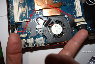
Carefully hide the monitor cable deep to the right of the left speaker and connect it to the appropriate connector. The arrows indicate where to connect the cable: 
With fastening connectors for loops and just wires, we work very carefully and “sensually”. Gently holding both parts, slowly apply an insertion force until a characteristic soft snap is felt. Depending on the connector, it can be very soft and not very clicky, but it is quite possible to feel it, in my opinion. You don't need to apply too much force, it could damage the connector's solder or something worse.
It is convenient to separate the trains with our homemade wooden "chisel". Its shape is a tribute to your ingenuity and love of comfort. It is usually convenient for it to be about 5-10 mm wide with a sharp enough sharpening so that it can be inserted into a narrow slot. Also, a wooden stick will not close the contacts when you accidentally touch it to the board.
The screws to install in the next step are shown with red arrows. Next, we connect the cables of the Power button with an LED, as well as the network card to the motherboard: 
These two cables do not have a plastic connector at the end, instead they have a pull tab for easy removal. The tongue and cable, pressed against each other, form a sufficiently rigid structure to be carefully inserted into the connector on the motherboard. With a fairly slow and careful application of force, you can feel that the train has entered to the end. You can evaluate this by attaching the end of the cable to the connector before inserting and estimating the length to which it should go. Also, with some skill, you can carefully try to use only the tongue in order to insert the end of the cable into place.
When we see during disassembly that there are many screw holes, and only some of them are occupied at this stage, it is better not to be lazy and at least write down or sketch, or better, take a picture of this moment. It's hard to remember these things. For example, the photo above shows that of all the holes at this stage, only two screws are required. The rest of the holes are for through use with the top and/or bottom cover.
Now it's time to connect the expansion boards on the other side of the motherboard. Do not forget to connect the connectors of the power wires, the battery board and the wi-fi antenna going to the monitor. 
We insert the Wi-Fi card into the right place in the mini PCI-E slot. Before this, we monitor the cleanliness of contacts. Do not touch the metal contact plates with your fingers. The card is fixed with two screws.
We do the same with the modem. Its connector is vertical. Gently press it until a characteristic smooth click. It is best to do this slowly to feel that the connector is fully seated. We also fix it with the corresponding screw from our “cash desk”: 
Now put the optical drive in place. Its shape also leaves no doubt about the correctness / incorrectness of the placement. We insert the connector in the same way as we did with the network card, without touching the contacts. The drive should be pushed into the slot from right to left when looking at an open laptop in a natural way. We fix it with a screw from the side of the back cover. 
The next step in the assembly will be connecting and attaching the top cover: 
I would like to immediately draw your attention to the fact that the operation of removing this cover, in my opinion, is the most potentially dangerous for both breakage and damage to the appearance of the device. There are two things to keep in mind when disassembling.
First - after you have unscrewed all the conceivable and inconceivable screws holding, in your opinion, the cover, you need to find where the plastic latches are located, which can (and most likely will) hold it in addition to the screws. There can be two breakdowns here - either inaccurate prying of the lid with something hard and flat, leaving unpleasant traces of “opening” the patient in the areas where the lower and upper lids meet, or you can break off the latch, which can lead to the joint being loose, in it gaps are formed. Therefore, for prying, I recommend using a flat tool made of a material that is obviously softer than the material of the covers. It can be a disposable Chinese stick, cut with a knife from the wide end to the state of a chisel, or a similar part made of soft plastic. I advise you to make such a “tool” manually, because due to its softness it lasts for a short time, after which it must be re-sharpened. However, this is a payment for the aesthetic pleasure of the joint in the case after assembly (if there was such a thing initially). After one side of the lid is left, which is held only by latches, it is useful to shake the lid up and down, thereby gently releasing it from their grip. At this point, the main thing is not to rush, because it is one of the most “traumatic” for the person being repaired.
Secondly - from the cover to the motherboard, as a rule, there are cables, the connectors of which can be located approximately in the center of the motherboard. It is quite easy to damage them in various parts. Therefore, after the cover has succumbed, carefully look under it, find out what and how it is connected to the motherboard, in order to carefully disconnect it without bringing the cables to critical deformation when lifting the cover.
In this case, the cables to the motherboard are quite accessible without lifting the cover.
By the way, Toshiba carefully indicated the marking of the screws for convenience. The presence of such marking (F number) on an empty thread also indicates that a screw needs to be driven on that assembly layer. 
Among the fastening of the loops there are connectors with a folding clamping plastic bar: 
We fold it back for installation, set the end of the cable clearly into a shallow recess for it (fix it in the transverse direction), and then stick it approximately along the dimples on the cable from the previous clamp. We close the plank. A properly clamped cable should hold on quite tightly. If it is removed, then you need to once again carefully and correctly position the cable in the recess for it and deepen it into the connector to the end before snapping it into place. Patience and accuracy when attaching cables will pay off when you do not have to disassemble the fully assembled device again, because some of the equipment on board will not work (in this case, the touchpad or the lights on the case, or the buttons for the player above the keyboard, for example).
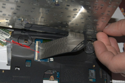
The keyboard is comfortable to put down, tilting it towards you. Then the cable will be easy to connect. Its connector is also equipped with a folding bar: 
The keyboard is very often fastened with latches on the sides. In our case, they are below and above (the lower ones are marked with arrows). There are still two screws on top (above the buttons F1-F2 and END-INS). The place above the keyboard is closed with a white plastic strip, which simply snaps into place. 
After snapping the plastic strip over the keyboard, the top of the case is ready.
Now back to the bottom cover. We install the screws as in the photo: 
We put the hard drive in place. As always, carefully and gently (and most importantly - to the end) combine the connectors. It is not necessary to screw in the disk case fixing screws yet. 
Queue the remaining back cover screws. The hard drive cover screws secure the hard drive to the body of the laptop. Finally, close and tighten the three screws of the central memory compartment, modem and network card. 
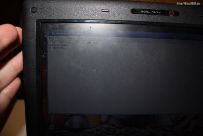
It remains to install the battery, remove the bandages and check the performance! 
After everything boots up successfully and there are no visible problems, it's good to get into the device manager on Windows or lspci and the like on Linux or system information on Mac to make sure that the peripherals are successfully recognized and working. After successfully passing the test, you can finally exhale, relax and enjoy the integrity of the device, which has just been distributed in an even layer on the table and boxes, and now breathes life.
How to fix a broken keyboard connector on a laptop motherboard
This guide describes how to fix a broken keyboard connector to a laptop motherboard. I am not claiming that my recommendations will work on any type of connector in any brand of laptop, but if I can help at least a few people, I will consider my mission accomplished.
Let's say the keyboard on your laptop stopped working properly and you decide to install a new keyboard yourself. You disassembled the laptop, removed the keyboard, tried to unlock the connector to disconnect the cable and. . . Here the YOKLMN part of the cable lock has broken!
What can you do? Unfortunately, you don't have many options. The keyboard connector is firmly soldered to the system board and cannot be replaced at home. If the connector has been damaged, you will need to replace the whole motherboard, use a laptop with an external USB keyboard, or try the following trick... Hopefully it will work, or alas....
The keyboard cable is blocked in the connector on the system board. To remove the keyboard, you must unlock the connector and remove the keyboard cable.
In the image below you see one of the most common connectors. It has a base (white in my case) and a locking clip (brown in my case). The keyboard cable is clamped between the blocking clamp and the base contacts.
To unlock the connector, you must move the clip approximately 2 millimeters in the direction indicated by the two yellow arrows in the figure.
IMPORTANT! The locking clip must remain attached to the connector base.
After that, you can remove the keyboard cable (green arrow) and remove the keyboard.
If you're not careful, you can move the clamp too far and break it.
The image below shows the clip with the left retainer broken off.
In the following image, both sides of the clamp are broken.
IMPORTANT! Don't throw away a broken clip, even if it looks completely useless.
If you insert the keyboard cable into the connector and do not secure it with the clamp, the cable will not make good contact with the pins in the connector and the keyboard will not work.
Here's how to fix a broken clip in place and make it work.
Insert the broken clip in the same way as before. In my case, both sides of the clamp are broken. What could be worse?
Carefully insert the keyboard cable into the connector. Please note, in this type of connector, the cable goes above the blocking clamp.
Carefully place the broken clip in place and use a small screwdriver to insert the clip behind the cable.
Fix the connection with adhesive tape, for reliability. The keyboard should work great.
The keyboard connector shown in the following image is very similar to the previous one. The only difference is that the keyboard cable is under the clip. Install it in the same way as the previous connector.
In the following image, you see a different type of keyboard connector. The loop is inserted vertically.
To unlock the connector, you will need to lift the locking clip (brown part) about 2 millimeters (two yellow arrows). After that, you can remove the keyboard cable (green arrow) and remove the keyboard.
If you apply too much force, you may break it.
In my example, the right side of the clamp is broken. But you can still use it!
Insert the keyboard cable into the connector, then insert the broken locking clip correctly (behind the cable in my case) and gently press it down.
Even with the latches broken, the clip keeps the cable in good contact with the connector base and the keyboard will work.
Here is the same connector, from the opposite side. You can't even tell if the locking clip is broken.
An article on how to disassemble a laptop and make minor repairs on its own without having to carry it to a service center. The article discusses the principle of replacing the RAM, WiFi module, hard drive and keyboard, as well as the complete dismantling of the motherboard.
Not so long ago, in addition to an ordinary stationary PC, having a laptop at home was considered almost a symbol of the wealth of the owners! Today, almost everyone has laptops of various types and sizes, starting with the first-grader Petenka, and ending with the pensioner Uncle Mitya on the bench :).
Recently, one can observe a certain decline in interest in laptops in favor of tablets and smartphones ... However, in my opinion, this trend is temporary, since touchscreens cannot yet fully replace the traditional keyboard and mouse. Therefore, it is still very, very early to "write off" portable computers, contrary to all forecasts! But sometimes they have to be repaired ...
Any technology tends to become obsolete and break down. And the more complex it is, the more often it will require attention. Laptops in this regard, unfortunately, are no exception ... The most common breakdowns are:
As you can see, there can be quite a few reasons for repair. In addition, the need to open the laptop may also be caused by the desire to make a planned upgrade with the addition of, for example, a new RAM bar or a more powerful processor. Therefore, in order not to languish, let's quickly get down to business :)
To disassemble a laptop at home, we need at least two screwdrivers: a small Phillips screwdriver for unscrewing the screws fixing the case and parts, as well as a thin flat one for carefully opening the case. In addition, it is desirable to think of some kind of organizer for sorting unscrewed screws and temporary storage of various small parts.
A digital camera may also come in handy, with which you will record all your actions. It will give you the opportunity not to forget what, where and how it was, respectively, to assemble the laptop so that there are no "extra" details :)
And today we will disassemble, in principle, a working Samsung N145 netbook from 2010:
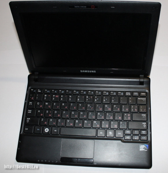
This laptop has already had to be repaired. The power button and the monitor matrix broke in it (as a result of which now there is a crack on the display case and it is sealed with glue, and therefore, we will not disassemble it). Otherwise, everything works fine and, I hope, will work for a long time :)
It is worth starting disassembly of any laptop by unplugging it, turning it over and disconnecting the battery. So, firstly, we will completely de-energize the device (respectively, we will avoid a short circuit), and secondly, we will open access to the case latches (in some models, a pair of case screws may be hidden under the battery). To remove the battery, you usually need to simultaneously pull the floating latches in different directions and pull the battery towards you.
Next, we carefully study the location of the screws holding the case and keyboard. Usually the latter are marked with the inscription "kbd" and there are from three to seven of them. The remaining screws (which are not marked in any way) will be body screws and it will be them that will need to be unscrewed in order to disassemble the laptop.

Before completely disassembling the laptop, please note that in some models, special revision holes may be provided on the back of the case for access to components such as RAM, hard drive, expansion ports, etc. These holes are usually covered with a small cap that is attached to the case with just one screw and allows easy access to the part without having to open the entire case.
In our netbook, the RAM bar is covered with such a cover, respectively, the screw holding the cover is marked as "Memory". By unscrewing it and removing the plug, we will be able, if necessary, to quickly replace the RAM bar:
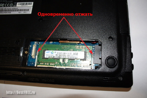
The memory card itself can be held in laptops either with a special clamping bar (which must be pushed aside), or (as in our case) due to two clamping metal plates on the sides. The latter are rigidly fixed, but can slightly bend away from the memory bar. Accordingly, in order to release it, both pressure plates must be pressed simultaneously. The board is inserted back with light pressure until the latches click.
Unfortunately, you may not be able to quickly access the components of your particular laptop model, so you can’t do without disassembly :)
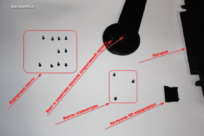
First of all, we need, as mentioned above, to remove the battery, unscrew all the screws that are on the back of the case, and also remove all plugs and other covers (if any). At this stage, the main thing to remember is which screw and where it was, since they come in different lengths and with different threads! A special plastic sorter with several compartments would be ideal for this. However, the cogs can be quite arranged in groups on a regular white sheet of A4 paper. The main thing is that you remember where each of them comes from! Here, for example, how I arranged all the details:
When everything is unscrewed, we pick up a flat screwdriver with a thin sting and find a place where you can insert it into the gap between the bottom and top covers of the laptop case. We do this carefully so as not to gouge the plastic. When the place is found, we slightly press the screwdriver up and down alternately to create a lever. As a rule, after pressing in the right direction, the plastic latches inside are released and the case will begin to open:

Similarly, we pass a screwdriver around the entire perimeter of the case. As a result, we should get a neatly removed undamaged bottom cover and access to the motherboard and laptop parts:

In order not to damage the cover, you need to remember one single rule: "DO NOT APPLY GREAT FORCE when pressing on the screwdriver" !!! If you notice that the cover does not want to open in one or more places, carefully check for hidden screws holding it in that area. They can be located under various stickers or under the rubber anti-slip feet on which your laptop rests on the table. Be careful and don't rush!
When the cover is safely removed, you can take a closer look at the internal structure of the laptop:

The following components must be present inside:
Optionally, there may also be:
Already at this stage of disassembly, we have access to almost all components that can be replaced, so you can no longer disassemble it. Just change the part that requires it and you can collect everything as it was. We are faced with the task of completely disassembling the entire laptop, so we will continue in order :)
We carefully look at our motherboard in order to identify the screws that still hold it. Two of them are found on the hard drive fasteners. We unscrew them and carefully take out the hard drive itself:

In laptops, hard drives are usually attached to the motherboard using a special "basket", which is fixed to the case with four screws, and connected to the motherboard using a special cable. To, for example, replace the hard drive with a new one (more productive or capacious), you just need to disconnect (again carefully) the cable plug from the old one, after which, when the old hard drive is already in our hands, remove it from the "basket" and replace on new.
Another screw that may prevent removal of the motherboard may be located on the WiFi module. Even if there is no retaining screw, this module will still have to be disconnected, since two wires go from it to the antenna, which is located in the display case.
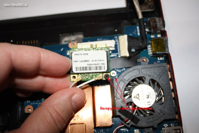
After you have removed all the major parts, carefully inspect the motherboard and unscrew the screws that remain unscrewed. At the same time, you do not need to unscrew the screws of the heatsink that cools the processor (unless you are going to change it or lubricate it with new thermal paste). When everything is unscrewed, the last step remains - disconnect the cables.
In our experimental netbook, after unscrewing all the screws that held the motherboard, the only "fasteners" were cables:
The easiest way to turn off the loops of sound and video. They are simply pulled out of the socket with a flat screwdriver (it is undesirable to pull the wires). Gently pry alternately on both sides and so slowly pull it out.
The situation is a little more complicated with the touchpad cable. It is pressed by a plug that needs to be pulled out. However, on the sides of this plug there are two small antennae that hold it in position. In order not to break these antennae, first drown them slightly, and only then pull them out.
The last step is to disable the keyboard. In principle, this can be done without disassembling the entire laptop. It is enough just to unscrew the screws marked "kbd" and the keyboard can already be pulled out. First you need to pry it with a thin screwdriver from above. Then, when the top edge is free, slightly pull up on the keyboard until the bottom edge pops out of the tabs. Now, everything is held only by the cable, which must be disconnected from the motherboard:
Keyboard cable attachments may vary from laptop to laptop. These can be plugs (as described in the case of the touchpad), pressure plates or simple plugs. To properly disconnect and not break, always use a search query such as "how to remove the keyboard on a laptop (your model)".
In the case of the Samsung N145 netbook, we are dealing with a cunning clamping mechanism, which is very similar to a regular plug. To open this mechanism, just pull it up, after which the cable will be released and we can pull it out :)
After disconnecting the last cable, nothing else holds our motherboard, and we can take it out, turn it over and see what its reverse side hides from us:

There is not so much here :) From what may be of interest to us, there is a keyboard cable lock that we already know, touchpad buttons and a BIOS battery. The latter may be of interest if you began to notice that your laptop did not turn on the first time or even stopped loading beyond the starting black screen. In this case, it may well be that the problem is in the dead battery, which needs to be replaced.
Alas, replacing the BIOS battery in a laptop is much more troublesome than in a regular PC, since it is not connected directly to a special socket, but through an adapter. The easiest, but also expensive way is to buy a similar battery in a complete assembly with an adapter and an adhesive part to fix it on the motherboard. But there is a better solution :)
If there is no ready-made battery or it costs indecently expensive, you can make it yourself :) To do this, remove the old one and free it from the black insulation to gain access to the wiring. Next, take a new battery of the same type and attach the removed wires to it (red is usually a plus, and black is a minus).
In order for the wires to hold and to insulate the battery itself, it would be best to place the resulting structure in a heat shrink tube of a suitable diameter. So we get an almost perfect adhesion of contacts without soldering and an appearance, almost like in the original :) Gluing the resulting design to its rightful place is easiest with thin double-sided tape.
Actually, we have everything on the motherboard. It remains to take a last look at what we have left on the case and can be collected :)

As you can see, of the spare parts on the case, only the speakers and the touchpad remained. If desired, they can also be removed and replaced, but it usually makes no sense to do this. Yes, and without soldering in this case, it is unlikely to do, and today not everyone can solder ... Therefore, on this we can consider the acquaintance with the laptop device to have taken place and it's time to reassemble :)
When assembling, we repeat all our steps in reverse order. This is where the photos that you took during disassembly (you took them? ;)) and correctly sorted screws can come in handy. When you put on the housing cover, do not rush to immediately screw it on. Fasten only the screws holding the keyboard and try to start the laptop:
If the operating system boots up, then try turning on regular Notepad and checking the operation of the keyboard by typing all the letters on it in turn. And only if everything works as it should, you can turn off the laptop and tighten the rest of the screws. Congratulations on a successful build!
As you can see, anyone can disassemble, replace a part and assemble their laptop back! The main thing, I repeat once again, is not to use brute force once again, think logically and act without haste. If you follow all these three rules, then in 70% of cases you will be able to "bring back to life" your laptop, which will serve you faithfully for more than one year!
Naturally, this article can only serve as a guide, since it considers the disassembly of only one laptop model (more precisely, a netbook). Before opening your laptop, I strongly recommend that you find detailed instructions on the Internet specifically for your model and follow it. If you work carefully and thoughtfully, then everything will work out for you. Good luck!
P.S. It is allowed to freely copy and quote this article, provided that an open active link to the source is indicated and the authorship of Ruslan Tertyshny is preserved.
There was a Sony KDL 26P3000 TV in the closet - not a bad television receiver at all and did not work for a long time, less than three years, but something happened to the image, it began to disappear. Professional specialists at the Sony service center easily agreed to “put it on its feet” for 12,000 rubles, but given that it costs 18,000, they politely refused. They bought a new TV, and this one was completely at my disposal. In anticipation of a banal disassembly into component components, I decided to check the conjecture expressed by a familiar radio amateur about a possible malfunction, which there is a chance to fix on my own.
To do this, it was necessary to remove the controller, disconnecting, including the cable coming from the panel. Usually everything is simple when someone has already done it before your eyes, but here there was a negative experience. The specialist who removed the controller last time took a long time to get used to it, and it didn’t work out right away, in a word, he was heartbroken. Well, the impression from this operation remained appropriate.

When I had a chance to do it myself, I coped with the lower connector without difficulty. Everything is logical and in plain sight, so to speak predictable. In the lower part of the connector, on the sides, there are clearly visible metal elements of the U-shaped profile, between which and the main plastic element there is a large free gap, which immediately suggests the need for their simultaneous compression and subsequent removal of the “plug” from the “socket”. When the “plug” is removed, the latch itself is clearly visible, through which the connector is locked (fixed).

But the upper connector turned out to be “inadequate”, no protruding elements, no recesses and grooves. All structural elements at first glance are equivalent, there are no major parts or minor ones. Rushed to the forum for help. The advice was simple, like all great things - "Pick up with your fingernail and pull!". The matter remained for small - to understand what to pick up. Armed with a flashlight, a magnifying glass, and in the end imbued, we understand. It seems that smart people did, but they created such a primitive (just kidding, of course).

In the working position, the clamping bar (the right side of the entire structure) is lowered (it would even be more correct to say it is latched) and holds the cable going to the liquid crystal panel. Here, under it, then you need to slip your fingernail to the radio amateur (of all the available repair tools, this one turned out to be the most effective in this operation and safe for the integrity of the connector). A small nuance, it is necessary to cling to the very edge of the bar, then it will not come off, but will turn on the tides available on the sides and become vertical, at the same time releasing the train. From the first, second and even third time, the nail may slip, but in the end the desired will be achieved. Which is clearly seen in the simple but visual video below.


