The power supply is a necessary thing in the arsenal of any radio amateur. And I propose to assemble a very simple, but at the same time stable circuit of such a device. The circuit is not difficult, and the set of parts for assembly is minimal. And now from words to deeds.
The following components are required for assembly:
BUT! All these details are presented exactly according to the diagram, and the choice of components depends on the characteristics of the transformer, and other conditions. Below are the components according to the diagram, but we will select them ourselves!
Transformer (12-25 V.)
Diode bridge for 2-6 A.
C1 1000uF 50V.
C2 100uF 50V.
R1 (the value is selected depending on the transformer, it is used to power the LED)
R2 200 ohm
R3 (variable resistor, also selected, its value depends on R1, but more on that later)
Chip LM317T
As well as the tools that will be needed during the work.

Here's the diagram right now:

The LM317 chip is a voltage regulator. It is on it that I will collect this device.
And so, let's start assembling.
Step 1. First you need to determine the resistance of resistors R1 and R3. The point is which transformer you choose. That is, you need to choose the correct denominations, and a special online calculator will help us with this. It can be found here at this link:
I hope you understand. I calculated the resistor R2, taking R1 = 180 ohms, and the output voltage is 30 V. The result is 4140 ohms. That is, I need a 5 kΩ resistor.

Step 3 First, I will explain what to solder where. To pins 1 and 2 - LED. 1 is the cathode, 2 is the anode. And we consider the resistor for it (R1) here:
To contacts 3, 4, 5 - a variable resistor. And 6 and 7 were not useful. It was conceived to connect a voltmeter. If you do not need it, then just edit the downloaded board. Well, if necessary, then install a jumper between 8 and 9 contacts. I made the payment on getinax, using the LUT method, etched in hydrogen peroxide (100 ml of peroxide + 30 g of citric acid + a teaspoon of salt).
Now about the transformer. I took the power transformer TS-150-1. It provides a voltage of 25 volts.

Step 4 Now we need to decide on the body. Without thinking twice, my choice fell on a case from an old computer power supply. By the way, my old PSU used to be in this building.

I took the front panel from an uninterruptible power supply, which fit very well in size.

This is how it will be installed:


To close the hole in the center, I glued a small piece of fiberboard, and drilled all the holes I needed. Well, I installed Banana connectors.


The power button is on the back. She is not in the photo yet. I fixed the transformer with its “native” nuts to the rear fan grille. He fit true to size.

And in the place where the board will be, I also glued a piece of fiberboard in order to avoid a short circuit.

Step 5. Now you need to install the board and radiator, solder all the necessary wires. And don't forget the fuse. I attached it on top of the transformer. In the photo it all looks somehow scary and not beautiful, but wearing it is not at all like that.

Today, when new technologies and electrical appliances appear almost every year, it is very difficult to do without some equipment at home. A particularly important role in our lives is given to power supplies. Any radio amateur should be able to assemble this device with his own hands.
In today's article, we will talk about how to make such an important electrical appliance in the home laboratory as the lm317 power supply. The scope of such equipment is huge, so the knowledge of how to assemble it with your own hands will be relevant and useful in everyday life.
The power supply is an important attribute of any amateur radio home workshop. The principle of operation of the power supply is that it can convert the voltage and current in the network to the parameter we need for powering and connecting various electrical appliances. At the same time, such a device provides high protection against short circuits.
The power supply can be of two different types:
In addition, the scheme that is used to assemble this type of power supply can be different - from the simplest to the most complex.
Note! If you are new to radio electronics, then you should choose simple circuits to begin with. Such a scheme will be clear to you and will allow you to quickly create a device for a wide variety of needs.
Approximate scheme
The decision to assemble a power supply on an lm317 chip greatly simplifies the assembly process. At the same time, the circuit itself is also simplified. Thanks to the microcircuit, it becomes possible to make a regulated power supply and provide power stabilization.
If you believe the comments left by radio amateurs, such an assembly is several times superior to domestic counterparts, while possessing large resources.
Now let's consider the principle of operation of the device, since when assembling a lm317 type power supply in order to be able to regulate the voltage indicator, as well as the current strength in the network, it is necessary to clearly know and understand this aspect. Without this, it is impossible to properly assemble the device, even if the circuit is quite simple.

Working PSU
The power supply type lm317 is characterized by the following principle of operation. The lm317 microcircuit is engaged in the regulation of the current strength at the output and contributes to the voltage drop. The voltage drop occurs across the resistor. The resistor across which the voltage drops occurs has a value of 1.25 V.
As a result, such a circuit allows, by changing the value of the resistor, to adjust the voltage and provide a change in the current strength indicator.

Chip
Note! If the soldering of the parts was carried out correctly, then such a device prevents the occurrence of a short circuit. Here, the quality of the parts themselves plays an important role in the assembly. Therefore, give preference to better products by buying them from trusted sellers.
In addition, it must be remembered that this scheme for assembling a power supply with the participation of the lm317 chip has some limitations. The lower limit limit is 0.8 ohm and the upper limit is 120 ohm. Thus, for the selection of a resistor in order for this circuit to function normally, one must be guided by the formula 0.8 The lm317 type power supply can be used to change the voltage and current parameter in the following situations: Note! Most often, the power supply is used in tandem with an LED strip. Thanks to this, you can get high-quality lighting in any room of the house. In this case, protection against short circuit will be at a sufficiently high level. Backlight This is a basic, but far from complete list of all situations in which you may need the help of a lm317 power supply. Assembled on the basis of the lm317 chip, the power supply has the following characteristics: Note! Such a load is quite enough to check the performance of home-made electrical structures. At the same time, the circuit used in this case will be quite simple and will allow a person with minimal knowledge of radio electronics to assemble the required device. It includes cheap and common parts that can be easily found on the market or in specialized stores. Approximate set of parts If you want to create an adjustable type of power supply on the lm317 chip to change the voltage and current parameter, you will need the following parts: It is worth noting that, depending on which scheme is planned to be used to assemble such a block, the possible list of parts required in the work will also change. Transformer Before we start assembling the lm317 adjustable type short circuit protected unit, it is necessary to buy all the parts and components required for the job. Here it must be remembered that the service life and quality of work of the assembled PSU will directly depend on the quality of the purchased radio engineering products. This part can be removed from any electrical appliance that is idle at home or has already broken. For example, a transformer can be removed from a TV, tape recorder, etc. Power transformer Some recommend including a TVK-110 brand transformer in the circuit. It was previously installed in black-and-white TVs in a frame scan unit. But there is one minus here - the output voltage here will be only 9 V, and the current strength will be small. Moreover, if you need to power a powerful electrical appliance, then this transformer will not cope with the load placed on it. At the same time, remember that their power should be at least 40 watts. To make a PSU on an lm317t micro-assembly for a DAC, you will need an output voltage in the range of 3.5-5 V. This is the voltage level that should be maintained in the circuit to power the microcontroller. After you have chosen the assembly scheme and acquired all the necessary components, you can get to work. As already mentioned, in our case, the assembly of an adjustable type power supply will be based on the lm317 chip. Note! The rectification type can be full-wave, single-half-wave, tripling, doubling, bridge. For a conventional PSU, it is better to take a bridge type of rectification. Rectifier circuit diagram Voltage stabilizer circuit Ready-made PSU option After that, we are guided by the chosen scheme, installing the remaining parts. As you can see, with a properly selected circuit, depending on your level of professionalism and knowledge of radio engineering, you can easily create an adjustable-type power supply based on the lm317 chip with your own hands. In order for you to succeed, you need to follow the assembly scheme, as well as purchase quality parts. As a result, you will get an excellent power supply with excellent characteristics - an indispensable assistant in the home laboratory of any radio amateur.
Sooner or later, any novice radio amateur is faced with the need to have a simple, reliable and inexpensive adjustable power supply to test their own crafts, and, of course, to test new “patients”. There are few options - either buy a ready-made block with the required characteristics in a store or from a more experienced craft colleague, or assemble the device yourself from improvised materials. Taking into account the prices for more or less high-quality SMPS with voltage regulation (on average from 15 to 80 USD), the conclusion suggests itself. One of the simplest and most versatile options is the LM 317 power supply. This is a popular and inexpensive adjustable linear voltage regulator, usually manufactured in the TO-220 package. You can find out which leg is responsible for what from the picture below. The main characteristics are: Let's take a closer look at the maximum current. The fact is that the LM 317 is a linear stabilizer. The "extra" voltage on it turns into heat, and the maximum heat pack of the microcircuit with an additional cooling radiator is 20 W, without it - about 2.5 W. Knowing the formula for calculating power, we can calculate how much current can actually be obtained under various conditions. For example, Uin=20 V, Uout=5 V – voltage drop Udrop = 15V. With a heat pack of 20 W, this means a maximum allowable current of 1.33 A (20 W / 15 V = 1.33 A). And without a radiator - only 0.15A. So in addition to radio components look for a radiator- some more massive one will do, from an old power amplifier, and you need to approach the choice of power source wisely. Very few details are needed: As you can see, there is very little work - the desoldering of parts can be done even by surface mounting, without compromising quality, provided that all contacts are carefully insulated and the power supply is survivable. After assembly, do not rush to connect the load to the block - first check the supply voltage at the output of the diode bridge, and then start the unit at idle and check the temperature of the stabilizer with your finger - it should be cool. Then connect the power from the unit to some load and check the voltage readings at the output - they should not change. You also need to observe the temperature regime - the optimal operating temperature of the LM 317 is 50 ... 70 degrees Celsius, and the more the microcircuit heats up, the worse the accuracy of voltage stabilization. If constant heavy loads are expected, for example, powering power amplifiers or electric motors, it is advisable not only to fix the microcircuit on a radiator, but also increase the capacitance of the smoothing capacitor up to 4700 uF and above. With a properly selected capacitance under load, the voltage will not sag. When you decide to get your own universal power supply, think about what would be better for you - to pay a decent amount for a ready-made solution, or to assemble the device yourself, using inexpensive components and amusing your own vanity, albeit a small, but, nevertheless, achievement. The cost of a do-it-yourself adjustable power supply is low - from the cost of the microcircuit itself (about 20 rubles) to 700–800 rubles when buying new parts in a store. Hello, today I will tell you how to make an adjustable power supply based on the lm317 chip. The circuit will be able to deliver up to 12 volts and 5 amps. Somehow recently, on the Internet, I came across one circuit of a very simple power supply with the ability to adjust the voltage. It was possible to regulate the voltage from 1 Volt to 36 Volts, depending on the output voltage on the secondary winding of the transformer. Take a close look at the LM317T in the circuit itself! The third leg (3) of the microcircuit clings to the capacitor C1, that is, the third leg is the INPUT, and the second leg (2) clings to the capacitor C2 and a 200 Ohm resistor and is the OUTPUT.Application area

The power supply, powered by the lm317 chip, will allow you to stop using random adapters, as well as periodically buy batteries.Device characteristics

Getting ready to assemble
![]()
Therefore, if you are not very well versed in components, it is best to buy only where you can be provided with a quality certificate for the products sold.
One of the most important parts in any assembly scheme will be the transformer. It is used to step down the voltage as a converter.![]()
Here, if there is a need for a powerful PSU, power transformers should be used.
You may also need minor changes to the secondary without affecting the primary.Assembling the power supply
The assembly goes like this:


All elements of the circuit can be placed in a case, for which plastic or aluminum sheet should be used. But you can give the PSU absolutely any shape that you yourself want. How to choose and install volume sensors for automatic light control
We don't want to buy, we want to create!
Components and diagram
 Just in case, we will separately explain why the voltage of the transformer is not more than 25 V. When rectified using a filter capacitor, the output voltage rises by the root of two, that is, approximately 1.44 times. Thus, having 25 V AC windings at the output, after the diode bridge and smoothing capacitor, the voltage will be about 35-36 V DC, which is quite close to the limit of the microcircuit. Keep this in mind when choosing capacitors and transformer!
A few nuances
 LM 317 has many analogues, both good and not so - be vigilant when choosing a product on the market! If the adjustment accuracy is important, you can change the value of the tuning resistor to 2.4 kOhm - the output voltage range, of course, will decrease, but accidentally touching the knob will hardly change the output voltage- and sometimes it is very important! Experiment with different ratings to make your power supply comfortable.
Power Supply Diagram

For assembly we need

Circuit Assembly
We will assemble the circuit by surface mounting, since there are few details. First, we attach the chips to the radiator, so it will be more convenient to assemble. By the way, it is not necessary to use three LMs. They are all connected in parallel, so you can get by with two or one. Now we solder all the leftmost legs to the potentiometer leg. We solder the plus of the capacitor to this leg, solder the minus to the other output. So that the capacitor does not interfere, I soldered it from the bottom of the potentiometer. 
To the leg of the potentiometer, to which the left legs of the microcircuits are soldered, we also solder a 100 Ohm resistor. We solder the middle legs of the microcircuits to the other end of the potentiometer (I have purple wires). 
Solder the diode to this leg of the resistor. We solder all the right legs of the microcircuit to the other leg of the diode (I have white wires). Plus, solder one wire, this will be the plus of the input. 
We solder two wires to the second output of the potentiometer (I have them black). This will be minus entry and exit. We also solder the wire (I have it red) to the resistor where the diode was previously soldered. This will be a plus. 
Now it remains to solder to the plus and minus of the input, plus and minus of the output through a 100 nF capacitor (100 nF = 0.1 uF, marking 104). 
Next, we solder a 2200 uF capacitor to the input, the plus leg is soldered to the plus of the input. 
On this, the production of the circuit is ready. 
Since the circuit outputs 4.5 amps and up to 12 volts, the input voltage must be at least the same. The potentiometer will already regulate the output voltage. For convenience, I advise you to put at least a voltmeter. I will not make a complete case, all I did was attach a radiator to a piece of fiberboard and screw a potentiometer. I also brought out the exit wires and screwed crocodiles to them. This is quite convenient. Next, I attached it all to the table. 

With the help of a transformer from a mains voltage of 220 volts, we get 25 volts, no more. Less is possible, more is not. Then we straighten the whole thing with a diode bridge and smooth out the ripples with the help of capacitor C1. All this is described in detail in the article how to get a constant voltage from an alternating voltage. And here is our most important trump card in the power supply - a highly stable voltage regulator chip LM317T. At the time of this writing, the price of this microcircuit was around 14 rubles. Even cheaper than a loaf of white bread.
LM317T is a voltage regulator. If the transformer produces up to 27-28 volts on the secondary winding, then we can easily regulate the voltage from 1.2 to 37 volts, but I would not raise the bar for more than 25 volts at the output of the transformer.
The microcircuit can be executed in the TO-220 package:

or in D2 Pack

It can pass a maximum current of 1.5 amps through itself, which is enough to power your electronic gadgets without a voltage drop. That is, we can give out a voltage of 36 Volts at a load current of up to 1.5 Amperes, and at the same time, our microcircuit will still give out 36 Volts as well - this, of course, ideally. In reality, fractions of a volt will drop, which is not very critical. With a large current in the load, it is more expedient to put this microcircuit on a radiator.
In order to assemble the circuit, we will also need a 6.8 Kilo-ohm variable resistor, maybe even 10 Ki-ohm, as well as a 200 Ohm fixed resistor, preferably from 1 watt. Well, at the output we put a capacitor of 100 microfarads. Absolutely simple scheme!
Previously, I had a very bad power supply still on transistors. I thought why not remake it? Here is the result ;-)
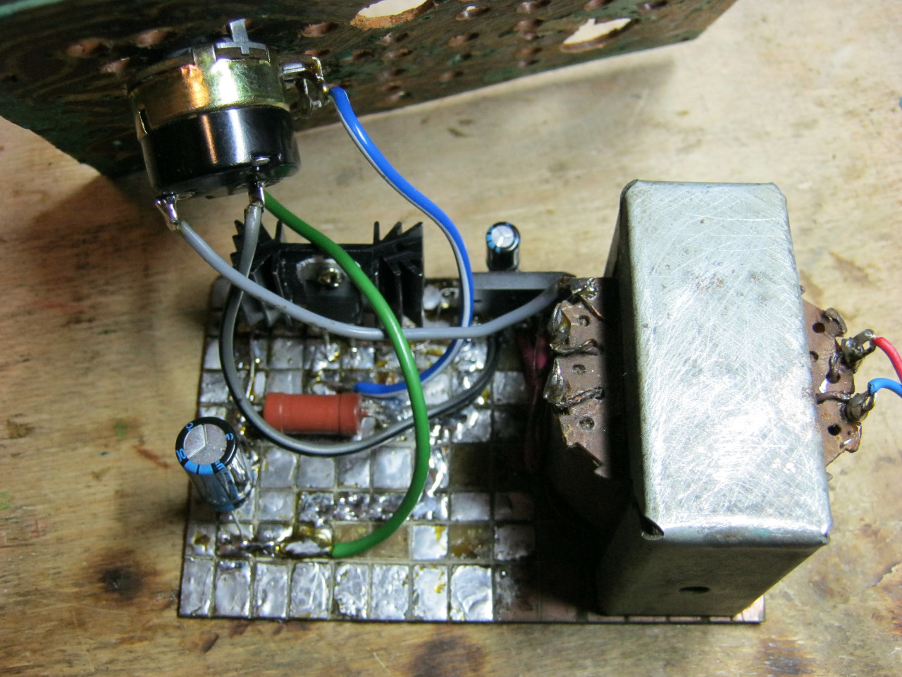
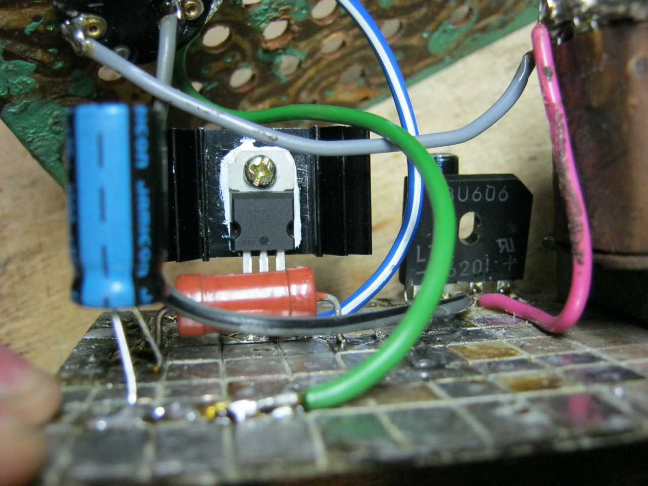
Here we see the GBU606 imported diode bridge. It is designed for current up to 6 amperes, which is more than enough for our power supply, since it will deliver a maximum of 1.5 amperes to the load. I put the LM-ku on the radiator using KPT-8 paste to improve heat transfer. Well, everything else, I think, is familiar to you.
And here is the antediluvian transformer, which gives me a voltage of 12 volts on the secondary winding.

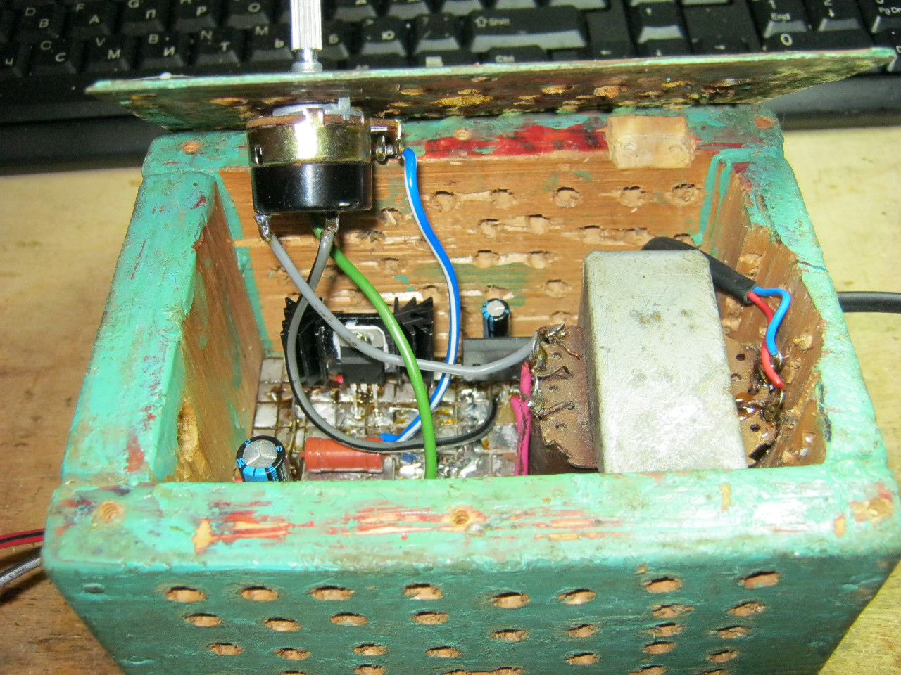
We carefully pack all this into the case and remove the wires.
So what do you think? ;-)

The minimum voltage I got was 1.25 Volts, and the maximum voltage was 15 Volts.

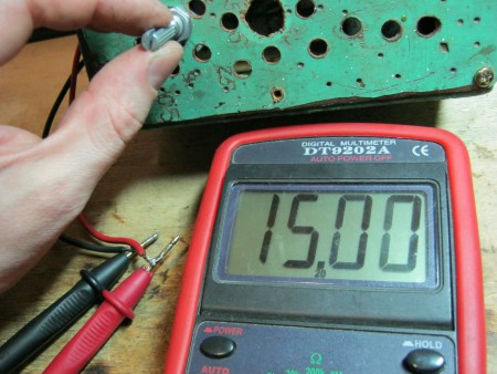
I put any voltage, in this case the most common 12 Volts and 5 Volts


Everything works with a bang!
This power supply is very convenient for adjusting the speed of a mini drill, which is used for drilling boards.

By the way, on Ali you can immediately find a ready-made set of this block without a transformer.

Too lazy to collect? You can take a ready-made 5 Ampere for less than $ 2:

You can view by this link.
If 5 Amperes is not enough, then you can look at 8 Amperes. It will be enough even for the most seasoned electronics engineer:


