Recently they brought me a Pioneer music center, model X-HM20, for repair. This malfunction will be a common occurrence for this “unit” and can be eliminated quite simply. I made a photo report with explanations, so if you know how to hold a soldering iron and a screwdriver in your hands, you can handle it just fine.
The characteristics of this device can be found on the website https://market.yandex.ru/product/7766678
The owner complained that the device behaved strangely for some time, it turned on, but somehow not confidently; to turn it on, you had to poke it (in the sense that you press the power button several times in a row) and knock, and after a while it turned on. And then it stopped turning on altogether.
Well, as experienced craftsmen used to say, “An autopsy will show.” And it showed: it showed that this would probably be a typical malfunction for this model; in most cases it would manifest itself exactly like this:
There are two options: A) Contact a radio equipment repair specialist. B) Repair it yourself. Yes Yes. exactly himself. This is not at all difficult for this malfunction. The only condition is that you still must be able to solder and have something to solder with, i.e. soldering iron, rosin, solder (tin) quite a bit. And at the nearest radio parts store you need to purchase two, not at all expensive, parts. I'll tell you about them and show you later.
Follow the description and photo.
So. We open the case, unscrew the four screws on the sides and four on the back, I think this will not cause any difficulties.
Further we're not in a hurry
, slowly and not much lift the lid. We get sophisticated, put our hand under the raised lid and disconnect the cable that goes from the Dock Station for iPod/iPhone to the main board. To do this, take the cable with your fingers and carefully pull it up, pulling it out of the connector. You will also see another wire there, which also needs to be disconnected from the connector by slightly pulling it. Let's look at the photo.

That's it, now that we have freed the cover from all connections, we can put it aside.
Pay attention to the following photo.

Two radio components are marked here, electrolytic capacitors with a nominal value of 16v-1000 Mk (Microfarads). They need to be replaced. If you feel their surface, they may even appear slightly swollen; this happens often, but not always.

I had in stock capacitors for a slightly higher voltage, but they were correspondingly larger, and since space allows, I soldered them. This is what happened.

Important: These radio components have a polarity, plus and minus, and they must be soldered taking into account this very polarity. The negative terminal is marked on the capacitor body, and on the board, in the place where they need to be soldered, a large bold dot indicates the side where the negative terminal of the capacitor should be turned (in the photo above you can see that the negative is facing down) Have you soldered it? That's it, let's try to turn it on! If everything is OK, then we assemble it, not forgetting to reconnect the cable and the wire with the connector.
A little about circuit design. This model implements a circuit using two power transformers, they can also be seen in the photo above. The small one is used to provide power to the control processor in standby mode and power the control relay. The large transformer, the one above which the capacitors are located, is the main one; it powers the entire circuit.
What happens is approximately the following: The control processor, powered by voltage from an additional, small transformer (it is this voltage that is filtered by those capacitors that had to be replaced), is in the “Dozing” standby mode but not completely asleep, it periodically “interrogates” the control buttons and checks whether a signal has arrived from the remote control? Isn't it time to wake up?
As soon as you give a command to turn on, the processor detects this and “tells all elements that it’s time to wake up”; it does this by supplying power to the main transformer control relay, in other words, connecting the transformer to the voltage network.
As a result, all necessary circuits receive voltage and are put into operation. This should be the case under normal conditions.
But gradually, the capacitors stopped coping with their work, the quality of the rectified voltage dropped, and for the same reason, the voltage level supplying the processor and relays also decreased. This explains the gradually increasing reluctance of the music center to turn on the first time until it is completely paralyzed.


Now the multimeter shows what is left of the capacitor capacity - 11.6 microfarads instead of the required 1000.
A simple replacement of dead containers will bring the device back to normal.
Good luck with the renovation!
Music is one of man's favorite pastimes. She accompanies him everywhere on the road, at work, school and, of course, at home. Good music, of course, is great, but we must not forget that to enjoy your favorite compositions you need high-quality sound. In order to achieve this, an electrical device such as a music center was invented. Over the course of a long time, its electronic components were adjusted and refined, all in order to expand its functionality, in particular, to improve sound. Today, music centers are structurally complex devices that consist of advanced electronics and modern mechanical elements. It is worth noting that the process of modernizing and repairing them with your own hands is still in full swing, and this despite the extensive and varied selection of products.
Musical equipment of this type is a universal electro-acoustic device designed for playing and recording audio files. It supports a wide range of audio formats that are designed to work with various types of audio media.
Modern music centers are complex electrical devices consisting of many complex electrical components and mechanical components.
They are platforms for installing film cassettes. This item of equipment is considered obsolete, however, it can still be found in certain models. When purchasing a music center, you should check whether the selected model of the device is equipped with a pair of decks. Otherwise, it is better not to purchase it, since if necessary, you will not be able to re-record music or listen to one cassette while rewinding another.
According to the control mechanism, the decks are of two types: mechanical - opened by pressing a button - and touch-sensitive (opened by a light touch).
An optical disc player is an integral part of any modern device.
The main component of an optical disc player is the optical drive. Basically, the optical drives included in modern centers are of the universal type, which is capable of supporting a wide range of various popular media formats.
It is worth noting that simple centers are equipped with an optical drive capable of playing only one disc. In more complex MCs, the drive is complemented by a changer - a device designed to simultaneously accommodate several discs (usually from three to seven) and play them sequentially.
When talking about optical disc players, it's worth mentioning the ways in which you can load discs into an optical drive.
There are a large number of music centers on the audio equipment market, which can be divided into front-loading and vertical-loading devices.
In addition to the methods described above, there are various boot mechanisms:
The following types of boot mechanisms are used in devices that are equipped with the ability to work with several disks at once. Such mechanisms include:
A radio tuner is an electronic device designed to receive signals coming from terrestrial radio stations.
Modern music centers can be equipped with both digital and analogue radio tuners. They all perform the same task - provide high-quality reception of radio programs in various audio frequency ranges (FM, AM, MW and LW), however, digital tuners have a number of advantages over analogue ones. Among which:
An equalizer (EQ, tone block) is a device that is used for special processing of an audio signal in a selected frequency range. It is an element that is part of almost all modern MCs, however, their structure and characteristics differ greatly (depending on the chosen model).
A device designed to store audio files intended for playback and directly record them. The capacity of hard drives depends on the manufacturer and usually ranges from 80 to 250 GB.
They are devices used to output audio information (play music). Depending on the configuration of the center, there may be a different number of speakers. Based on the number of speakers and their design features, music centers are built on the basis of three acoustic systems:
Microsystem:
The simplest models of music centers are built on the basis of a stereo pair (two speakers containing one speaker each). In this case, the sound signal is divided into two parts, which are transmitted through one of the channels (broadband speaker) left or right.
Mini and microsystems:
They are used in more complex music centers, where each speaker uses more than 2 speakers. In this case, the audio frequency spectrum is divided into several narrow frequency bands (subbands). Each of these bands has its own characteristics and therefore the speakers included in the speakers have their own individual design, which is characteristic of a particular band. The difference in designs leads to an improvement in the reproduced sound.
The advantage is high sound quality and purity.
The disadvantage is the complexity of manufacturing (due to the fact that it is necessary to create an individual design for each speaker).
A separate and most interesting type of speaker system is two-way.
This type of system is used in music centers that use speakers that are equipped with two speakers with fundamentally different designs. In this case, the frequency range is divided into two wide bands. As a rule, systems of this type use: a speaker of a combined type that reproduces both low and medium frequencies, and a high-frequency one.
The number of frequency bands and channels can be found in the technical description of the MC of the selected model.
In addition to the various types of acoustic systems discussed above, the following electronic components and modules are used to generate a sound signal and improve its properties.
It is used to convert information that is recorded on digital disc tracks into a multi-channel audio signal. If the latest decoder models are installed in the music center, it is possible to increase the format of the audio system and improve its sound quality.
Digital sound processor ( Digital Sound Processor) carries out complex processing of the audio signal.
Using the processor, sound processing is performed, which is based on the required frequency, number of bands, as well as the sound atmosphere of the room used as the installation location for the audio system.
Previously, the sound processor was an element that was installed only in expensive models of music centers, but now it is used in almost any center.
Implements the ability to roughly adjust the audio signal through amplification/attenuation, which is carried out by an adjustable high- and low-pass filter.
During the operation of music centers, various malfunctions may occur, for example, electronic components and modules may fail or mechanical parts may be damaged. Let's look at them below.
The most common malfunctions that users of music centers complain about are:
"doesn't read discs"
One of the likely causes of the malfunction may be damage or burnout of the fuse located in the input circuit of the power supply.
To carry out diagnostics, follow these steps:
Remember that to replace an element, you must select a fuse of the same rating (can be found in the device diagram or on the element itself) as the damaged one! Otherwise, a number of unpleasant moments are possible, for example, the microcircuit of the right or left channel may burn out.
If after replacing the fuse everything is fine and nothing happened to the microcircuits, then just in case, let’s check them for this:
The TDA-7265 microcircuit also must be replaced if it burns out as a result of soldering a new fuse (see video for possible consequences of installing an incorrectly selected fuse).
And also quite often there are problems with amplification and sound reproduction quality. These malfunctions can be divided into the following:
In most cases, such malfunctions arise due to the fact that over time, during operation, the laser head becomes dirty and ages. These (contamination and aging), in turn, contribute to a decrease in the transparency of the plastic lens. Collectively or individually, these phenomena can manifest themselves in different ways, for example, after inserting a disc into a music center, the player begins to scan the information tracks of the media and tries to read the data, but some time later the reading stops, or the device read the information and started playback, however, During the process, noises arise, accompanied by frequent glitches when playing music.
In order to diagnose these malfunctions, we check the functionality of the laser itself and the degree of transparency of the lens for this:
One of the simple ways to eliminate failures and incorrect playback of CDs is to clean the laser head, which consists of two steps:
At the first stage, we clean the lens. To do this, follow these steps:
At the second stage, we proceed to cleaning the prism (we do this only if cleaning the lens did not lead to a positive result). For this:
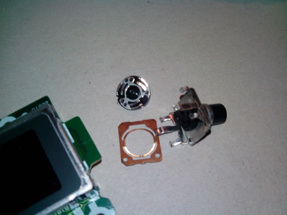
These malfunctions mainly occur in music centers that are built on a digital control system (microprocessor). The thing is that instead of the usual variable resistor used to regulate the volume level, these devices use a valcoder (encoder) - a special sensor.
Rotation of the encoder causes the corresponding contacts to close. The processor, in turn, monitors the direction of rotation of the “regulator” and, based on the information received, changes the gain in the path. Accordingly, if the contacts have oxidized or become dirty during operation, then malfunctions will periodically appear and normal sound control will be disrupted.
This malfunction does not require complex diagnostics, since it can be carried out visually, so we will immediately proceed to troubleshooting. In order to clean the contacts of the encoder, do the following:
Let's disassemble the encoder:
After that:
Among specialists and novice radio amateurs, a certain method for diagnosing music centers that have problems with amplification and sound quality has long been established. It is quite simple so anyone can use it. At its first stage, you need to check whether the speakers are working and evaluate the sound quality.
Checking the speakers is carried out in any case (if there is a hoarse sound, its absence, and so on) as it will help narrow down the scope of troubleshooting and more or less accurately determine their source.

After completing these steps, there are two possible options:
At the second diagnostic stage, you should check the integrity of the connection between the output connector and the contact copper tracks on the device control board. (only if the speakers are working properly), since it also affects the sound quality and can: cause wheezing or contribute to the sudden disappearance/appearance of sound.
In order to assess the quality of soldering, we perform the following steps:

I would like to note that contact damage or poor-quality soldering is usually found immediately, since these things are clearly visible.
For the purpose of prevention, as well as to eliminate possible degradation of soldering - small gaps between the connector contact and the edges of the board groove - that form in the device after long-term operation due to overheating or high mechanical load. The connector contacts should be soldered.
In this case, problems may be associated with the incorrect operation of two microcircuits: an amplifier designed to amplify audio frequency power (APP), a processor, and a signal switch.
To carry out diagnostics and accurately determine the faulty microcircuit, we perform the following steps:
If the malfunction goes away when each mode is turned on, most likely the cause of the problem lies in the UMZCH microcircuit. However, the cause of the malfunction may be a malfunction of another unit of the device, for example, incorrect operation of the sound processor chip responsible for switching signals.
This situation can lead to confusion and lead to the fact that we will look for a fault in the wrong node. To prevent this from happening, we will carry out additional diagnostics:
By following these simple steps, it is possible to significantly narrow the area of troubleshooting, since if the headphones reproduce high-quality and “smooth” sound, this indicates the proper operation of all components of the audio path: sound processor, signal switcher, preamplifiers. Accordingly, the malfunction occurred in that part of the electronic circuit that provides signal power amplification.
If, after carrying out the steps described above, the malfunction remains, this means that the UMChZ microcircuit is faulty or it is not working correctly (out of two channels, the sound is reproduced in only one or the sound passes through both channels, but in one of them with distortion) . Accordingly, this microcircuit (can be of different series, for example, TDA 8588J. 4 or STK 403-070) must be replaced with a new one.
We check the device according to the method described above and determine the malfunction. If the diagnostic results reveal that the UMCHZ is not working correctly, it should be removed and replaced with a new one.
Before we begin dismantling the microcircuit, we will do the following:

After desoldering the microcircuit, do the following:
These malfunctions can be caused by a break in the coil winding or the coil winding touching the magnetic system of the speakers. However, before disassembling the speakers, you should check the functionality of the music center speakers by connecting other speakers (as described in the method and perform other steps).
Please note that this repair is very complex and time-consuming. It should not be performed without proper experience and skills, as well as the availability of tools for the job!
If during the inspection of the circuit no defects (problems with microcircuits) were identified, and the faults disappeared, then it is necessary to repair the speakers. For this:

Before you start rewinding the coil, you need to disassemble the speaker. For this:

The process of disassembling the speaker is completed and now you can start rewinding the coil.
Before assembling the speaker, check whether the coil is touching the magnetic system. For this:
We assemble speakers:
Remember that work at all stages of eliminating these two faults must be done very carefully. Especially when assembling a speaker with a rewound coil; otherwise, if the assembly is not done carefully, the noise may remain, but the sound quality will nevertheless become higher.
In the modern audio market, all kinds of music centers are sold. Each of them has its own characteristics, which are determined by the components and modules used in the development and creation of the device. Some modern centers have a built-in Wi-Fi module, which allows you to go online and download music. In addition, most MCs can be refurbished and supplemented with speakers, external acoustic systems, amplifiers, desktop equalizers and other devices related to sound in one way or another.
The music center is designed to read media and listen to radio broadcasts. The receiver module is easy to detect after disassembly by the presence of a thin metal (foil) screen. Inside the steel box: high-frequency amplifier, local oscillator, mixer, and other stages. Electronic microcircuits cannot be repaired; individual spare parts are more expensive than the device as a whole. Music centers use a superheterodyne circuit with one frequency conversion. The final stage is a stereo low-frequency amplifier, through which sound passes through the music center to the speakers. Isolation through transistor switches controlled by the position of the regulator on the front panel of the household appliance. Repairing a music center with your own hands is not always possible; it’s interesting to see what’s inside.
Let's try to see how to fix a Samsung music center yourself. We came across a useful technical description and will read it. We'll leave the repair of Sony music centers for next time. The radio receivers in music centers are wide-wave, and the creators did not bother too much with the circuit; they made two paths:
We avoid describing the subtleties of dividing the ranges, just remember: small FM antennas receive a frequency modulated signal. Paths can be implemented on one chip (like KA2295Q) or separately. Before the detector, both paths are incompatible due to the specifics of signal processing. You can amplify a weak one and mix it with the local oscillator frequency, but don’t interfere with subtlety: each stage of the Earth still has a limited frequency band. We repeat, up to and including the detector, the paths go separately. The advantage of the integrated solution is described by its high specialization; automatic frequency adjustment eliminates worries about uncertain signal reception by the music center.
Many people cannot imagine a device that refuses to play cassettes. There are usually two decks, they work alternately for playback, and are controlled mechanically. At the circuit level, the amplifier switches to the desired head. The tape drive mechanism has one motor, pulls the tape, the reels are slightly spring-loaded. The recording and playback paths are separate, you can write:
Today a chip for decrypting MP3 and other formats is being added. The flow enters the low frequency amplifier. It is not difficult to notice the microcircuit; the case is placed under a good-quality heatsink of respectable size. Here the lion's share of the energy consumed by the music center is lost; other stages work with a low-amplitude signal.

Simultaneous playback from a tape recorder and a laser disc is not provided. Would make sense when mixing home original recordings. The microphone works in all modes. Allows you to record karaoke on tape and sing along with artists on the radio.
Read-write preamplifiers are assembled using one chip, for example, K22291. The film erase current is generated by a transistor generator. It is clear that the frequency differs greatly from the sound one. We must not forget about a software or microcircuit-implemented equalizer. Simpler than a steamed turnip, a cascade that places emphasis on a selected part of the spectrum of the recording being played. It is customary to listen to rock while showering your neighbors with bass; a low-pass filter makes a contribution.
The operation of the laser disc drive is controlled by a controller responsible for focusing and tracking tracks. Samsung uses the KA9220 microcircuit, which controls the motors through the KA9258 drive device and amplifiers. There are two drive motors, one rotates the disk, the second positions the head. The KA9220 controller directs the work and pre-deciphers the head signal. Further sound processing is carried out by the KS9282 signal processor, the waves are corrected and interpolated. To eliminate high-frequency interference, filtering is carried out using the KA9270 microcircuit.

The music center must have a system controller. A microcircuit that controls the operating modes of the equipment. Some Samsung music centers use MICOM LC866216 for these purposes. For interactivity, the controller is supplemented with an indication panel and keys. Through the interface, the user controls the music center. The infrared radiation receiver of the control panel is located on the front panel. It is worth noting: the central controller analyzes the position of the volume knob and generates signals for adjusting the low-frequency amplifier (a microcircuit on a large radiator). The control bus is digital, so you don’t need to look for a transistor-based volume control.
Switching power supply. Contains input signal filters, a high-frequency pulse generator that controls a transistor switch, output filters, and sometimes rectifiers using Schottky diodes. The voltages are stabilizing. The transformer and fuses are placed on a separate board. The device refuses to turn on - it’s logical to start repairing a music center with your own hands from here. There are several supply voltages, be sure to ring the secondary windings.

Let's consider the receiver. In the case of Samsung music centers in the VHF range, the telescopic antenna signal comes to the preselector (a set of resonant channel filtering circuits plus a high-frequency amplifier). The following is a typical circuit: mixer with local oscillator, detector. The restructuring of the circuits is carried out by varicaps using the voltage of the automatic frequency control microcircuit of the LM7000 music center. For smoothing, the signal is filtered before being sent to the varicaps. The receiver local oscillator frequency is controlled by the LM7000 chip. Signal selection is carried out mainly in an intermediate frequency amplifier. Before it, the frequency jumps, here it takes a fixed value (10.7 MHz). Therefore, piezoceramic filters are easier to set up.
The KA2295Q microcircuit, as mentioned above, is represented by a combination of an amplitude and frequency detector and selects the useful signal from the carrier. This includes a path of medium and long waves. Including local oscillators, mixers, amplifiers. The first stage is equipped with automatic gain control. For correct operation of the frequency detector of the music center, a phase-shifting oscillatory circuit is required. Automatic gain control works based on the mixer signal. It is necessary that the intermediate frequency amplifier and frequency converter do not enter cutoff mode.
From the frequency modulation detector, the signal is supplied to the pilot tone stereo decoder through a filter. Information about the presence of a stereo signal is provided to the central controller. You can force select the mode using the regulator. The central controller of the music center receives information about the state of the signal and controls the formation of sound. Channel balancing occurs using a variable resistor. The filtered signal enters the TDA 7318 chip, where the main low-frequency amplifier stage of the music center begins.
In the MF and LW bands, loop antennas with transformer coupling are used. The device of the music center includes transistors for switching channels across bands. The heterodynes are switched as needed by electronic switches. The adjustment is carried out by varicaps, the adjustment is made using AFC signals. The high-frequency amplifier is broadband and is not switched in the music center. The intermediate frequency in the MW and LW bands is 450 kHz (typical value). The detected signal, without passing through the pilot-tone circuit, is immediately fed to the filters and to the output amplifier of the receiver. As for the MF and LW, the circuit communicates with the central controller of the music center about the fact of frequency capture, which helps the “brain” to be aware of events.
It remains to add that there are two channels, it’s just that the sound is different on FM frequencies, and the same on LW and MW. Which is what is called, in fact, stereo and mono. When reading cassettes and discs, the situation is similar; you can artificially bring separate playback to continuous playback. The differences between the channels of the music center are leveled out.
It is important to understand that the main types of faults can be represented by a careful study of the diagram. The review did not contain a complete and complete description of the music center, we will return to this later. The master must know in advance what will break. Repairing music centers yourself will seem like child's play.
Always look for original factory diagrams and descriptions before digging into the electronic insides of household appliances. Microchip drawings are open to free access by copyright holders. The purpose of the chips is described on the manufacturers' websites.
Instructions
Find out the cause of the malfunction of the music center. The most frequent and obvious breakdowns can be associated with a violation of its parameters or the absence of sound as such. Check the sound speakers (speakers) with a tester for voltage.
Use a working speaker from another device to make sure that the reason for the loss of sound does not lie in the center itself. If, after connecting working speakers, there is still no sound, there is a problem with the music device itself.
Disassemble the body of the music center. To do this, unscrew all the mounting screws with a Phillips screwdriver and remove the rear protective cover of the device. This will get you to the main board and you can inspect it.
Inspect the connection between the input connector and the copper traces on the main board of the music center. Use a soldering iron to restore the soldering in those places where it is damaged. To do this, it is better to use low-temperature solders that melt at 100 degrees, or generally conductive glue, so as not to damage the integrity of small parts of the board.
Play the music center in all possible modes (radio, cassettes, MP3 player) and check for irregularities. If in all modes the sound is reproduced with the same noise, then the problem is in the output amplification path. Damage to the power amplifier. To fix it, replace the damaged amplifier chip with a working one.
After troubleshooting, carefully inspect the main board again. It may have poorly soldered areas, swollen capacitors, darkened traces and other defects that may soon make themselves felt. Replace all “suspicious” parts. In this way, you will prevent another breakdown of your music center and extend the life of your equipment.
Sources:
Sometimes the music center does not have an MP3 function, but the pocket player does. But the player, unlike a music center, is not capable of sounding loudly. To correct this drawback, you need to connect the player and the center to each other.
Instructions
First, check your stereo for RCA input jacks on the front panel, labeled AUX or PHONO. Don't confuse them with headphone or microphone jacks - they are not only made to a different standard, but are also designed for a different purpose.
If you do not find such sockets, then carefully, so as not to tear off any cables, turn the music center with the back wall towards you. You will probably find such nests there. Do not confuse them with sockets for other purposes, which can also be made according to the RCA standard.
Now take the unnecessary headphones. Cut off the sound emitters from them. Purchase two RCA type plugs. Strip the wires that went to the sound emitter. One of the pairs consists of a clear (or yellow) and a red (or orange) wire, and the other has a blue or green wire instead of a red or orange wire. Connect all colorless or yellow wires to the ring contacts of the plugs, and the red (orange) and blue (green) wires to the pins.
Connect the cable to the player and music center. On the last one, select the mode called AUX or PHONO. If it has several inputs, they may be designated AUX1, AUX2 and the like. When searching for an input, set both the player and the center to a low volume. In the future, set the volume on the player so that the center preamplifier is not overloaded, and then make adjustments from the center side.
To prevent the player's battery from draining, connect the device to a special power supply that emulates a USB port. You can also use a powered USB hub that is connected to the unit but not to the computer. Remember that if the player is powered not by a battery, but by a battery, charging the latter in any way is not allowed. Using a music center together with a player does not exclude the possibility of switching it to other modes if necessary.
Some novice radio amateurs are not eager to take on the repair of rather complex electronic devices, such as CD or MP3 players, computers or stereo systems. In fact, most of the malfunctions of the same music center are quite easy to fix, having minimal knowledge in the field of electronics and a little experience in handling equipment.

You will need
Instructions
Determine what type of problem you need to fix. It is quite difficult to cover all the problems with music centers. Most often you have to deal with the absence of sound or a violation of its parameters (timbre, signal amplification, frequency characteristics).
Start looking for the cause of the sound problem by checking the speakers. To check, connect another column (speaker) with a resistance of 4-8 Ohms. You can use a working speaker from an old TV or tape recorder. Typically, the load resistance value is indicated on the back wall of the device case next to the corresponding connector.
If, after connecting a working speaker, sound appears or its quality is restored, the fault should be looked for in the speakers. Otherwise, you will have to look at the internal circuits of the music center.
If you hear wheezing during playback, and the sound appears and disappears, look for the cause of the malfunction in a broken connection between the input connector and the contact copper tracks on the main board of the playing device. Restore the soldering in places where it is broken.
Check the operation of the music center in all modes: receiver, cassette deck, MP3 player. If the sound disturbance occurs in all three cases, the failure is most likely associated with the output amplification path, namely the audio power amplifier. To finally make sure of this, connect your headphones to the “Phone” jack, remembering to turn down the volume. The absence of sound in this case indicates the failure of the specified amplifier. Replace the amplifier chip with a working one.
Even if the described actions eliminated the problem, inspect the printed circuit board to identify poorly soldered areas, “swelling” of electrolytic capacitors, darkened traces and other defective installation elements. Replace identified faulty elements. Such prevention will prevent larger malfunctions during further operation of the music center.
Firmware programs are periodically released separately for each hardware model. A software update is necessary in cases where malfunctions occur or the previous firmware version becomes outdated.


