The proposed programmer is based on a publication from the Radio magazine No. 2, 2004, “Programming modern PIC16, PIC12 on PonyProg”. This is my first programmer that I used to flash PIC chips at home. The programmer is a simplified version of the JDM programmer, the original circuit has an RS-232 to TTL converter in the form of a MAX232 chip, it is more versatile, but you can’t assemble it “on your knee”. This circuit does not have any active components at all, does not contain scarce parts and is very simple, it can be assembled without the use of a printed circuit board.
Rice. 1: Schematic diagram of the programmer.
Description of the scheme
The scheme of the programmer is shown in fig. 1. Resistors in the circuits CLK (clocking), DATA (information), Upp (programming voltage) serve to limit the flowing current. PIC controllers are protected from breakdown by built-in zener diodes, so some compatibility of TTL and RS-232 logic is obtained. In the presented circuit, there are diodes VD1, VD2, which “take away” positive voltage from the COM port relative to pin 5 and transfer it to the controller’s power supply, due to which, in some cases, it is possible to get rid of an additional power source.
Establishment
In practice, it does not always happen that this programmer will work without adjustment, from the 1st time, because. the operation of this scheme is highly dependent on the parameters of the COM port. However, on two Gigabyte 8IPE1000 and WinFast motherboards under XP, everything worked right away for me. If you are too lazy to deal with a non-working, more complex programmer circuit, then you should try to assemble this one. Here are some things that might affect:
The newer mat. board, the developers pay less attention to these ports, because these ports have long become obsolete. You can get rid of this by purchasing a USB-COM adapter, although again, the purchased device may not be suitable. The required parameters are as follows: the variable voltage must change at least -10V to +10V (log. 0 and 1) relative to the 5th pin of the connector. The output current must be at least such that when a 2.7 kΩ resistor is connected between the 5th pin and the pin under test, the voltage does not drop below 10V (I have not seen such boards myself). Also, the port must correctly determine the voltages coming from the controller, at a voltage level close to 0V, but not more than 2V, zero is detected, and, accordingly, at above 2V, one is detected.
Also problems can arise from the software.
This is especially true for LINUX OS, because due to the presence of emulators like wine, VirtualBox ports may not work correctly, and a lot of features are required from them. I will touch on these issues in more detail in another article.
Knowing these features, let's start building.
For this, it is highly desirable to have the ICProg 1.05D program.
In the program menu, you must first select in the settings resp. port (COM1. COM2), select JDM programmer. Then open the "Hardware Check" window, in the "Settings" menu. In this menu, you need to check the boxes in turn and measure the voltage at the contacts of the connected connector with a voltmeter. If the voltage parameters do not correspond to the norm, then unfortunately, this may be the cause of inoperability, then you will have to assemble a circuit with an RS-232 TTL converter. Having checked all the checkboxes, you need to make sure that a supply voltage of about 5V is formed on the zener diode. If the voltages are normal and there are no installation errors, then everything should work. We put the controller in the socket, open the firmware, program it. Checkboxes like "Invert data out" do not need to be enabled (all are unchecked). Also, do not forget that some batches of controllers may not have quite standard parameters, and they cannot be flashed, in such cases with this programmer you can only try to reduce the supply voltage from 5V to 3-4V by connecting the corresponding. zener diode, look at the controller for erroneous activation of the LVP mode (low voltage programming), how to prevent, you can read on the Internet for a specific type of controller. You can probably increase the programming voltage of a problem controller only by complicating the circuit by introducing an amplifier stage with a common emitter, powered from an additional power source.
Now more about the problem with the power supply of the device. The programmer was tested with ICProg programs and console picprog under Linux, it should work with anyone that supports JDM if you connect an additional power source (it is connected through a 1kΩ resistor to the zener diode, diodes with resistors in this case can be completely excluded). The fact is that the programmer control algorithms for individual software are different, the ICProg program is the most unpretentious. It was noticed that in Windows this program raised the required supply voltage on the unused pin 2, the same program under the emulator in Linux to another mat. The board was no longer able to do this, however, a way out was found by taking power from the programming voltage. In general, with ICProg, I think you can use this programmer without additional power. With other software, this is unlikely to be guaranteed, for example, the “native” from the Ubuntu picprog repositories without power simply does not detect the programmer, displaying the message “JDM hardware not found”. It probably either receives some data without applying the programming voltage, or does it too quickly, so that the filter capacitor has not yet had time to charge.
JDM programmer I used for controllers PIC16F676, PIC16F630 And PIC16F629. From the original, my version differs in that the programming voltage Vpp can be applied before the supply voltage vdd for reprogramming controllers. For this purpose, the upper transistor in the circuit is used. It opens when the voltage on pin 3 of the DB9F socket reaches approximately 8 V with respect to pin 5 of the socket, or 13 V with respect to the minus of the controller Vss. Switch Vdd_Vpp in the closed state allows the supply voltage vdd appear on the controller outputs before the programming voltage Vpp.
For programming, a COM port will be used, which will use the following pins - 3, 4, 5, 7 and 8. The circuit has the ability to program memory chips of the series 24cXX. To do this, the lower 8 contacts are used in the DIP16 block, the first contact of the microcircuit is inserted into the fifth pin of the block. Jumper J1 allows you to disable write protection.


The lower transistor in the circuit, as before, is used to shift voltages, since the plus power supply of the controller vdd connects to pin 5 of the socket - the common wire of the port, and minus the power Vss is obtained using diodes connected to pins 3 and 7 of the socket, and a zener diode.

Transistors in the JDM programmer used 2SC945 And BC548, diodes - 1N4148. Capacitor u1 should be placed as close as possible to the power pins of the microcontroller. The 1k resistor is optional if the 10k resistor and jumper J1 are installed on the DIP16 block.

This programmer successfully works with programs and
It just so happened that I started my acquaintance with microcontrollers with AVR. PIC microcontrollers for the time being, for the time being - bypassed. But, nevertheless, they also have unique, interesting to repeat, designs! But these microcontrollers also need to be flashed. I am writing this article mainly for myself. In order not to forget the technology, how to flash a PIC microcontroller without problems and senseless loss of time.
For the first circuit - I tried for a long time and hard to make a PIC programmer according to the circuits found on the Internet - nothing happened. It's a shame, but I had to turn to a friend to flash the MK. But this is not the point - to constantly run around acquaintances! The same friend also advised a simple scheme that works from the COM port. But even when I put it together, it still didn't work. After all, it’s not enough to assemble a programmer - you also need to set up a program for it, which we will flash. And this is exactly what I didn't get. A whole cloud of instructions on the Internet, and few of them helped me ...
Then, I managed to flash one microcontroller. But since I was flashing it under conditions of a severe lack of time, I didn’t think to save at least a link to the instruction. And after all, I did not find it later. Therefore, I repeat - I am writing an article in order to have my own instructions.
So, a programmer for PIC microcontrollers. Simple, although not 5 wires like for AVR microcontrollers, which I still use today. Here is the diagram: 
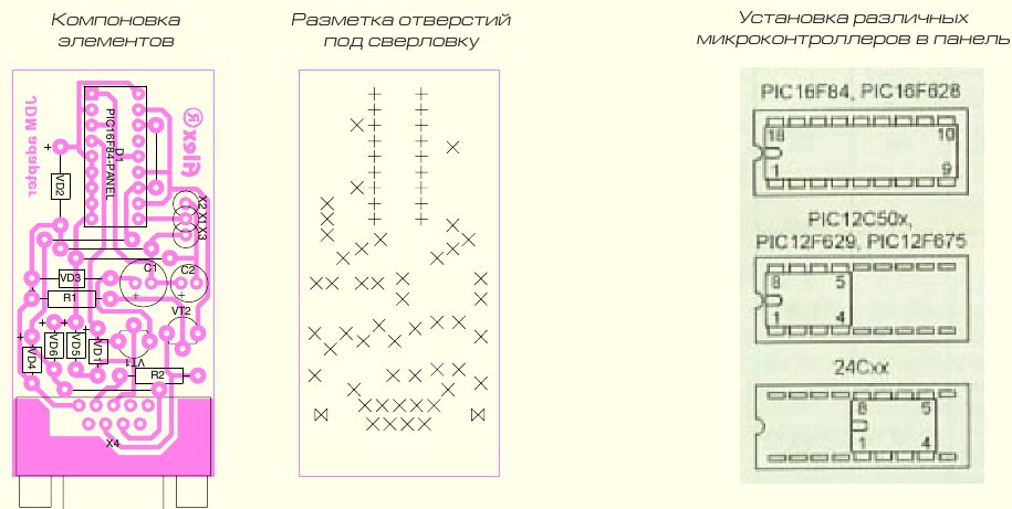
Here is the circuit board (). 
The COM connector is soldered with pins directly to the pads (the main thing is not to get confused with the numbering). The second row of pins is connected to the board with small jumpers (I said very incomprehensibly, yeah). I'll try to give a photo ... even though it's scary (I don't have a normal camera right now).  The most vicious thing is that for PIC microcontrollers, 12 volts are needed for firmware. And better not 12, but a little more. Let's say 13. Or 13.5 (by the way, experts - correct me in the comments if I'm wrong. Please.). 12 volts can still be obtained somewhere. Where is 13? I just got out of the situation - I took a freshly charged lithium-polymer battery, which had 12.6 volts. Well, or even a four-cell battery, with its 16 volts (I flashed one PIC this way - no problem).
But I digress again. So - instructions for firmware PIC microcontrollers. We are looking for the WinPIC800 program (unfortunately, the simple and popular icprog did not work for me) and configure it as shown in the screenshot.
 After that, open the firmware file, connect the microcontroller and flash it.
It is the simplest design for flashing controllers of the PIC family. The undeniable advantages - simplicity, compactness, power without an external source of this classic programmer circuit made it very popular among radio amateurs, especially since the circuit is already 5 years old, and during this time it has established itself as a simple and reliable tool for working with microcontrollers.
Schematic diagram of the programmer for pic controllers:

Power supply for the circuit itself is not required, because the COM port of the computer is used for this, through which the microcontroller firmware is controlled. For low-voltage programming mode, 5v is enough, but all options for changing (fuses) may not be available. The connector for connecting the COM-9 port was mounted directly on the printed circuit board of the PIC programmer - it turned out very convenient.

You can plug the board without extra cords directly into the port. tested on various computers and when programming MK series 12F, 16F and 18F, showed high quality firmware. The proposed scheme allows programming PIC12F509, PIC16F84A, PIC16F628 microcontrollers. For example, recently, using the proposed programmer, a microcontroller was successfully flashed for.
For programming, WinPic800 is used - one of the best programs for programming PIC controllers. The program allows you to perform operations for microcontrollers of the PIC family: reading, writing, erasing, checking FLASH and EEPROM memory and setting configuration bits.
It is not a problem for many radio amateurs to quickly assemble a circuit they like on a microcontroller. But many beginners to work with microcontrollers are faced with the question of how to program it. One of the simplest options for programmers is the JDM programmer.
This program runs on Windows XP. Allows programming PIC controllers of the medium family (PIC16Fxxx) via the computer's COM port. The programmer connection indicator (in the upper right corner of the window) in the absence of a programmer on the port selected in the settings turns red. If the programmer is connected, the program detects it and the indicator in the upper right corner takes the form shown in Figure 1.
The control panel is located on the left side of the program window. This panel can be minimized by clicking on the button in the toolbar or by clicking on the left edge of the window (this is convenient when the program window is maximized to full screen).


To transfer 1 bit of information to the microcontroller, you must set 0 or 1 (depending on the value of the bit) on the data line ( DATA) and create a voltage drop (transition from 1 to 0) on the clock line ( CLOCK).
One bit for the controller is not enough. He waits after five more to take this package of 6 bits as a command. The controller really likes commands, and they should consist of exactly 6 bits - this is the nature of the PIC 16.
Here is the list and meaning of the commands that the PIC is able to understand. There are not so many commands - the vocabulary of this controller is small, but one should not think that it is completely stupid - there are devices with fewer commands
"LoadConfiguration" 000000 - Load configuration
"LoadDataForDataMemory" - 000011 - Loading data into data memory (EEPROM)
"IncrementAddress" 000110 - Increase the address of the PC MK
"ReadDataFromProgramMemory" 000100 - Reading data from program memory
"ReadDataFromDataMemory" 000101 - Reading data from data memory (EEPROM)
"BeginProgrammingOnlyCycle" 011000 - Start programming cycle
"BulkEraseProgramMemory" 001001 - Complete erasure of program memory
"BulkEraseDataMemory" 001011 - Complete erasing of data memory (EEPROM)
The controller reacts to these commands in different ways. In different ways, after issuing the command, you need to continue the conversation with him.
In order to start a full-fledged programming process, it is also necessary to apply a voltage of 12 volts to the MCLR output of the controller, then apply a supply voltage to it. It is in this sequence of voltage supply that there is a certain meaning. After power up, if the PIC is configured to run from the internal RC oscillator, it can start executing its own program, which is not allowed when programming, as a failure is inevitable.
Pre-feeding 12 volts to the MCLR avoids this scenario.
When writing information to the flash memory of MK programs after the command
"LoadDataForProgramMemory" 000010 - Loading data into program memory
it is necessary to send the data itself to the controller - 16 bits,
which look like this:
“0xxxxxxxxxxxxx 0”.
The crosses in this word are the data itself, and the zeros around the edges are sent as a frame - this is the standard for PIC 16. There are only 14 significant bits in a word. This series of controllers has a 14-bit command representation format.
After the transmission of the data word is completed, the PIC waits for the next command.
Since our goal is to write a word to the MK program memory, the next command should be the command
"BeginEraseProgrammingCycle" 001000 - Start programming cycle
Having received it, the controller is disconnected from the outside world for 6 milliseconds, which it needs to complete the recording process.
The signals at the pins of the microcontroller are generated by a computer using special programs - programmers. COM, LPT or USB ports can serve for signal transmission. Programs such as PonyProg, IsProg, WinPic800 work with the JDM programmer.

One of the questions when connecting the programmer to a computer is the question - how to provide selective isolation. In order to avoid damage to the COM port in the event of a malfunction in the circuit. Some circuits use the MAX232 chip, which provides selective isolation and signal level matching. In this scheme, the issue is resolved more simply - using battery power. The level of the signal coming from the computer is limited by the zener diodes VD1, VD2, and VD3. Despite the simplicity of the JDM programmer circuit, most types of PIC microcontrollers can be programmed with it.
The jumper between the pins COM6(DSR) and COM7(RTS) is designed so that the program can determine that the programmer is connected to the computer.
The pin assignment for microcontrollers of the PIC16Fxxx series, depending on the type of case, is standard in most cases, but if there is any doubt about this, then it is most reliable to check the datasheet for a specific instance of the MK. Part of the documentation is present on the Russian site http://microchip.ru The full collection of datasheets and other documentation is on the website of the manufacturer of PIC microcontrollers: http://microchip.com


