If computer malfunctions occur, system diagnostics are required. One of the first to be tested is the power supply. Therefore, it is important for an active user to know how to check the power supply.
Key characteristics of the power supply
The presence of a reliable and high-quality unit in a computer is extremely important for each component of the system. In this case, uninterrupted and error-free operation of the computer will be ensured. What is a power supply and why is checking the computer power supply so important?
A computer power supply (PSU) is a secondary source that supplies the computer with electricity. Its main purpose is that power is supplied to the computer nodes in the form of direct current, and the mains voltage is converted to the required values.
The functional feature of the power supply is based on stabilization and protection against minor disturbances in the main voltage. The power supply also takes part in cooling the machine system elements. Therefore, it is so important to diagnose this component, which is practically the most important part of a computer of any kind. Since a malfunction in the power supply negatively affects the entire device.
(banner_123_block-pitaniya)
There are special standards that a power supply installed on a computer must comply with. First of all, it should work normally at a voltage for a network of 220 v - 180-264 v, the frequency is suitable 47-63 hertz. The unit must withstand sudden interruptions from the power source. When choosing a power supply, you should also pay attention to the connectors, which are divided into the following:
- supply of HDD and SSD master devices;
- motherboard supply;
- GPU graphics adapter supply;
- CPU supply.

PSUs have a coefficient of performance (efficiency) - the amount of energy that powers the computer. A high efficiency rate has a number of advantages. Among them are minimal electricity consumption; slight noise as it operates at lower speeds; longer service life, because temperatures are low, overheating does not occur; less heating due to reduced heat that needs to be dissipated, etc. As a result, the remaining elements of the system receive “high-quality food,” which means the entire computer works smoothly and lasts.
The table shows approximate consumption options.
If the calculations correspond to 250 W, then it is better to take it with a reserve - 400-500 W.
What do you need to know before you start testing your computer power supply?
Testing a computer power supply involves working under voltage. You need to be very careful to avoid an accident. Before checking the computer power supply, it is necessary to inspect the integrity of the braid of each cable. Under no circumstances should parts be touched with wet, bare hands. If you do not have enough experience in carrying out such operations, it is better to contact a specialist.
During diagnostic activities, it is important to remember that replacement diodes must be rated at 300 volts or higher. They must also carry a current of at least 1 ampere. Remember, after changing the diode bridge, you do not need to turn on the device from the network, because you need to check all the components at once.
Checking the power supply occurs in several ways. The first and simplest is to visually assess the external state of the BP. If there are inflated electrolytic capacitors and varistors, then the power supply protection is broken. The parts urgently need to be replaced with new ones.

If such a visual test of the power supply does not give positive answers, then you can use one of the diagnostic options - a computer program, a multimeter, a volt-ohmmeter, a special computer power supply tester (such devices sometimes show inaccurate readings).
One of the most common methods of testing a power supply is using a multimeter.
Step-by-step procedure for diagnosing a power supply using a multimeter
So, if the computer is unstable, suddenly turns off, a blue screen appears, or problems arise when loading, it is worth checking the power supply. This process occurs in several stages. First you should examine the cooling. To do this, you can touch the top of the system unit, where the power supply is located. If you feel obvious heat, then the power supply overheats. The reason for this is a breakdown of the cooling fan in the power supply. After a little testing with a screwdriver, which can easily spin the blades a few revolutions, if the fan is working properly, we decide on further actions. If everything is fine, clean the fan from dust and start the computer. If the fan malfunctions, it should be replaced. Now that we've put this part in order, let's figure out how to check the power supply without a computer.
To carry out diagnostics, it is not necessary to remove the power supply from the computer itself.
But for convenient work, you can still take it out.
Checking the voltage supply
- Turn off your computer- we finish the work, wait for the device to completely turn off, then on the back wall of the power supply you need to turn off the switch. Now we leave the network.
- Open the computer lid- disconnect the power supply from other components of the device. The cables must be removed one by one, and it is important to capture a picture of the correct position of the cables using a photo or video.

- We do the load- the computer turns off, but the test occurs under load. To do this, connect the cooler with a special connector. Don't forget about the 220V cable.
- Take a replacement wire- a paper clip in the shape of the letter U is inserted into the power supply after turning it off, you can also use a wire of a suitable diameter.
- Press the largest connector (20/24)- it is usually connected to the motherboard.
- Find contacts 15, 16 (green and black)- in order to touch these contacts with a paper clip.
- Insert a paper clip into contacts 15,16- after which be sure to release it and you can connect the power supply to the network and turn on the switch.

- Check the operation of the fan - if the cooler turns on, it means that the power supply is conducting current, it is working properly. If it doesn’t work, check the contact with the paper clip again and try again. If there is no result, the power supply does not work.
This is not the end of checking the computer power supply. This was a current conductivity diagnostic. Next, you need to test the operation of the power supply. The computer power supply tester is based on the use of a multimeter.
Testing the unit's operation
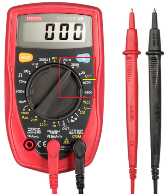
- We switch the multimeter to continuous current mode (voltage up to 20 W).

- Disconnect the power supply from the network.
- Using a handy device - a paper clip - we bring the power supply into working condition, connect the load through the optical drive. If the cooler does not spin, the power supply is faulty.
- We measure the voltage with a multimeter - we plug the black probe into the Molex connector, which is located opposite the black wire (middle connector). We insert the red probe one by one into the contacts on the wide cable and monitor the readings on the multimeter.

- In accordance with the pinout diagram of the power supply contacts, we determine the required voltage indicators in the operating state of the power supply. If the indicators do not match, this is a sign of a unit malfunction.
For ease of verification, we present a pinout diagram of the power supply contacts.
|
|
1
|
13
|
|
+3.3V
|
|
|
+3.3V
|
+3.3V
|
|
|
-12V
|
Ground
|
|
|
Ground
|
+5V
|
|
|
Power On
|
Ground
|
|
|
Ground
|
+5V
|
|
|
Ground
|
Ground
|
|
|
Ground
|
Power Good
|
|
|
Reserved
|
+5V Standby
|
|
|
+5V
|
+12V
|
|
|
+5V
|
+12V
|
|
|
+5V
|
+3.3V
|
|
|
Ground
|
|
|
12
|
24
|
|
As an example, the red wires have a voltage of - 5V, if your indicator is 4V - this is a clear sign that the power supply test showed a negative result and your power supply is faulty.
If you find a breakdown in the power supply, you can disassemble it and try to repair it. To do this, you need to have a basic knowledge of the operation of electrical devices. So, remove the cover, remove the dust and begin visual testing. What should you pay attention to? We are looking for elements that have blackening, swelling of capacitors, and looking for broken wires. It is necessary to inspect the inductor (inductor). A fuse or resistor may also blow.

Didn't find anything? We turn the board over and look at the solder tracks and connections. We are looking for sealed elements that could simply come off due to overheating or a manufacturing defect. The tracks that conduct current could burn out. In this situation, we simply replace the faulty components, and the device will be in working order. If you cannot fix the problem, contact a specialist. But don’t forget, if the power supply is under warranty, you should take it to a service center without opening the box.
Upon completion of testing, it is important to collect all contacts and connect according to the previously taken photograph. Remember, if your power supply is working properly, but problems with your computer continue, the reason for such operation of the device may be hidden in other components. Test the system further until you find the cause and eliminate it.
What will help extend the life of the power supply?
To prevent diagnostics of the computer power supply from becoming a frequent process, it is important to adhere to several rules for the safe operation of the power supply. First of all, check how securely and firmly the power supply is secured in the system unit. When installing components with higher power, the load on the power supply also increases. Therefore, you should make sure that the conductor and semiconductor components will not overheat. It’s better to immediately install a power supply with a power reserve, even when purchasing a computer. A good owner will monitor not only the power supply to his car, but will also promptly and regularly clean the insides of dust, which fills all the parts and makes their work difficult.
In order not to think about how to check the health of the computer power supply, it is important to ensure the constancy of the incoming alternating voltage and protect against sudden shutdown. To do this, just install an uninterruptible power supply and this problem will fade into the background.

In addition to the power supply itself, you also need to monitor the fan that cools the power supply. Periodically it is necessary to clean and change the lubricant.

So, the rules for choosing a device:
- do not buy very cheap power supplies because the quality will be appropriate;
- You shouldn't chase after Vata. For a computer with a more powerful gaming video card, it is worth choosing indicators - up to 550 W. For the rest, 350-400W will be enough;
- When purchasing a power supply, keep an eye on the price/Vata ratio. The larger the Wat, the more expensive the model;
- a quality block will weigh much more than a fake.
You should always adhere to the rules and monitor the safe operation of your computer. But this does not mean that your computer is immune from failure. If you hear a strong smell of burning wires, expect trouble. After all, the device itself, which may have been purchased from a defective batch, can lead to such an outcome. If there is no warranty on the power supply, you should try to test it yourself, if there is no result, you need to contact a specialist.
Well, in order for the test result to please you, try to carry out diagnostics whenever you suspect a unit malfunction. Then there will be more chances to fix it and continue using your favorite computer.
So, there are several ways to check the operation of a computer's power supply. Here we learned how you can do it yourself if you have basic knowledge of electronics. Follow the instructions and the diagnosis will be successful.
(banner_123_block-pitaniya)
Video instruction
The article we bring to your attention describes the methodology we use for testing power supplies - until now, individual parts of this description have been scattered across various articles with tests of power supplies, which is not very convenient for those who want to quickly familiarize themselves with the methodology based on its current state.
This material is updated as the methodology develops and improves, so some of the methods reflected in it may not be used in our old articles with power supply tests - this only means that the method was developed after the publication of the corresponding article. You will find a list of changes made to the article at the end.
The article can be quite clearly divided into three parts: in the first, we will briefly list the block parameters we check and the conditions for these checks, and also explain the technical meaning of these parameters. In Part 2, we will mention a number of terms often used by block manufacturers for marketing purposes and explain them. The third part will be of interest to those who want to familiarize themselves in more detail with the technical features of the construction and operation of our stand for testing power supplies.
The guiding and guiding document for us in developing the methodology described below was the standard
, the latest version of which can be found at FormFactors.org. At the moment, it is included as an integral part of a more general document called
Power Supply Design Guide for Desktop Platform Form Factors, which describes blocks not only of ATX, but also of other formats (CFX, TFX, SFX, and so on). Although PSDG is not formally a mandatory standard for all power supply manufacturers, we a priori believe that unless otherwise explicitly stated for a computer power supply (that is, it is a unit that is in regular retail sale and intended for general use , and not any specific computer model from a particular manufacturer), it must comply with PSDG requirements.
You can view the test results for specific power supply models in our catalog: "
Catalog of tested power supplies".
Visual inspection of the power supply
Of course, the first stage of testing is a visual inspection of the block. In addition to aesthetic pleasure (or, conversely, disappointment), it also gives us a number of quite interesting indicators of the quality of the product.
First, of course, is the quality of the case. Metal thickness, rigidity, assembly features (for example, the body can be made of thin steel, but fastened with seven or eight bolts instead of the usual four), the quality of the block's painting...
Secondly, the quality of internal installation. All power supplies passing through our laboratory are necessarily opened, examined inside and photographed. We do not focus on small details and do not list all the parts found in the block along with their denominations - this, of course, would give the articles a scientific appearance, but in practice in most cases it is completely meaningless. However, if a block is made according to some generally relatively non-standard scheme, we try to describe it in general terms, as well as explain the reasons why the block designers could choose such a scheme. And, of course, if we notice any serious flaws in the quality of workmanship - for example, sloppy soldering - we will definitely mention them.
Thirdly, the passport parameters of the block. In the case of, let's say, inexpensive products, it is often possible to draw some conclusions about the quality based on them - for example, if the total power of the unit indicated on the label turns out to be clearly greater than the sum of the products of the currents and voltages indicated there.
Also, of course, we list the cables and connectors available on the unit and indicate their length. We write the latter as a sum in which the first number is equal to the distance from the power supply to the first connector, the second number is equal to the distance between the first and second connectors, and so on. For the cable shown in the figure above, the entry will look like this: “removable cable with three power connectors for SATA hard drives, length 60+15+15 cm.”
Full power operation
The most intuitive and therefore most popular characteristic among users is the full power of the power supply. The unit label indicates the so-called long-term power, that is, the power with which the unit can operate indefinitely. Sometimes the peak power is indicated next to it - as a rule, the unit can operate with it for no more than a minute. Some not very conscientious manufacturers indicate either only peak power, or long-term power, but only at room temperature - accordingly, when working inside a real computer, where the air temperature is higher than room temperature, the permissible power of such a power supply is lower. According to recommendations
ATX 12V Power Supply Design Guide, a fundamental document on the operation of computer power supplies, the unit must operate with the load power indicated on it at an air temperature of up to 50 ° C - and some manufacturers explicitly mention this temperature to avoid discrepancies.
In our tests, however, the operation of the unit at full power is tested under mild conditions - at room temperature, about 22...25 °C. The unit operates with the maximum permissible load for at least half an hour, if during this time no incidents occur with it, the test is considered successfully passed.
At the moment, our installation allows us to fully load units with a power of up to 1350 W.
Cross-load characteristics
Despite the fact that a computer power supply is a source of several different voltages at the same time, the main ones being +12 V, +5 V, +3.3 V, in most models there is a common stabilizer for the first two voltages. In his work, he focuses on the arithmetic mean between two controlled voltages - this scheme is called “group stabilization”.
Both the disadvantages and advantages of this design are obvious: on the one hand, cost reduction, on the other, the dependence of voltages on each other. Let’s say, if we increase the load on the +12 V bus, the corresponding voltage sags and the unit’s stabilizer tries to “pull” it to the previous level - but, since it simultaneously stabilizes +5 V, they increase
both voltage. The stabilizer considers the situation corrected when the average deviation of both voltages from the nominal is zero - but in this situation this means that the +12 V voltage will be slightly lower than the nominal, and +5 V will be slightly higher; if we raise the first, then the second will immediately increase, if we lower the second, the first will also decrease.
Of course, block developers make some efforts to mitigate this problem - the easiest way to evaluate their effectiveness is with the help of the so-called cross-load characteristics graphs (abbreviated CLO).
Example of a KNH schedule
The horizontal axis of the graph shows the load on the +12 V bus of the unit under test (if it has several lines with this voltage, the total load on them), and the vertical axis shows the total load on the +5 V and +3.3 V buses. Accordingly, each a point on the graph corresponds to a certain block load balance between these buses. For greater clarity, we not only depict on the KNH graphs the zone in which the output loads of the unit do not exceed permissible limits, but also indicate their deviations from the nominal in different colors - from green (deviation less than 1%) to red (deviation from 4 to 5 %). A deviation of more than 5% is considered unacceptable.
Let's say, in the above graph we see that the voltage of +12 V (it was built specifically for it) of the tested unit is kept well, a significant part of the graph is filled with green - and only with a strong imbalance of loads towards the +5 V and +3 buses, 3V it goes red.
In addition, on the left, bottom and right of the graph is limited by the minimum and maximum permissible load of the block - but the uneven upper edge is due to stresses exceeding the 5 percent limit. According to the standard, the power supply can no longer be used for its intended purpose in this load range.
Area of typical loads on the KNH graph
Of course, it is also of great importance in which area of the graph the voltage deviates more from the nominal value. In the picture above, the area of power consumption that is typical for modern computers is shaded - all of their most powerful components (video cards, processors...) are now powered by the +12 V bus, so the load on it can be very large. But on the +5 V and +3.3 V buses, in fact, only hard drives and motherboard components remain, so their consumption very rarely exceeds several tens of watts even in computers that are very powerful by modern standards.
If you compare the above graphs of the two blocks, you can clearly see that the first of them turns red in an area that is insignificant for modern computers, but the second, alas, is the opposite. Therefore, although in general both blocks showed similar results over the entire load range, in practice the first will be preferable.
Since during the test we monitor all three main buses of the power supply - +12 V, +5 V and +3.3 V - then the power supplies in the articles are presented in the form of an animated three-frame image, each frame of which corresponds to the voltage deviation on one of the mentioned tires
Recently, power supplies with independent stabilization of output voltages have also become increasingly widespread, in which the classic circuit is supplemented with additional stabilizers according to the so-called saturable core circuit. Such blocks demonstrate a significantly lower correlation between output voltages - as a rule, the KNH graphs for them are replete with green color.
Fan speed and temperature rise
The efficiency of the unit's cooling system can be considered from two perspectives - from the point of view of noise and from the point of view of heating. Obviously, achieving good performance on both of these points is very problematic: good cooling can be achieved by installing a more powerful fan, but then we will lose in noise - and vice versa.
To evaluate the cooling efficiency of the block, we step by step change its load from 50 W to the maximum permissible, at each stage giving the block 20...30 minutes to warm up - during this time its temperature reaches a constant level. After warming up, using a Velleman DTO2234 optical tachometer, the rotation speed of the unit’s fan is measured, and using a Fluke 54 II two-channel digital thermometer, the temperature difference between the cold air entering the unit and the heated air leaving it is measured.
Of course, ideally both numbers should be minimal. If both the temperature and the fan speed are high, this tells us that the cooling system is poorly designed.
Of course, all modern units have adjustable fan speed - however, in practice, the initial speed can vary greatly (that is, the speed at minimum load; it is very important, since it determines the noise of the unit at moments when the computer is not loaded with anything - and therefore the fans video cards and processor rotate at minimum speed), as well as a graph of the dependence of speed on load. For example, in power supplies of the lower price category, a single thermistor is often used to regulate the fan speed without any additional circuits - in this case, the speed can change by only 10...15%, which is difficult to even call adjustment.
Many power supply manufacturers specify either the noise level in decibels or the fan speed in revolutions per minute. Both are often accompanied by a clever marketing ploy - noise and speed are measured at a temperature of 18 °C. The resulting figure is usually very beautiful (for example, a noise level of 16 dBA), but does not carry any meaning - in a real computer the air temperature will be 10...15 °C higher. Another trick we came across was to indicate for a unit with two different types of fans the characteristics of only the slower one.
Output voltage ripple
The principle of operation of a switching power supply - and all computer units are switching - is based on the operation of a step-down power transformer at a frequency significantly higher than the frequency of the alternating current in the supply network, which makes it possible to reduce the dimensions of this transformer many times.
The alternating mains voltage (with a frequency of 50 or 60 Hz, depending on the country) at the input of the unit is rectified and smoothed, after which it is supplied to a transistor switch, which converts the direct voltage back into alternating voltage, but with a frequency three orders of magnitude higher - from 60 to 120 kHz, depending on the power supply model. This voltage is supplied to a high-frequency transformer, which lowers it to the values we need (12 V, 5 V...), after which it is straightened and smoothed again. Ideally, the output voltage of the unit should be strictly constant - but in reality, of course, it is impossible to completely smooth out the alternating high-frequency current. Standard
requires that the range (distance from minimum to maximum) of the residual ripple of the output voltages of power supplies at maximum load does not exceed 50 mV for the +5 V and +3.3 V buses and 120 mV for the +12 V bus.
When testing the unit, we take oscillograms of its main output voltages at maximum load using a Velleman PCSU1000 dual-channel oscilloscope and present them in the form of a general graph:

The top line on it corresponds to the +5 V bus, the middle line – +12 V, the bottom – +3.3 V. In the picture above, for convenience, the maximum permissible ripple values are clearly shown on the right: as you can see, in this power supply the +12 V bus fits it’s easy to fit into them, the +5 V bus is difficult, and the +3.3 V bus doesn’t fit at all. High narrow peaks on the oscillogram of the last voltage tell us that the unit cannot cope with filtering the highest frequency noise - as a rule, this is a consequence of the use of insufficiently good electrolytic capacitors, the efficiency of which decreases significantly with increasing frequency.
In practice, if the power supply ripple range exceeds the permissible limits, it can negatively affect the stability of the computer and also cause interference with sound cards and similar equipment.
Efficiency
If above we considered only the output parameters of the power supply, then when measuring efficiency, its input parameters are already taken into account - what percentage of the power received from the supply network the unit converts into the power it supplies to the load. The difference, of course, goes to useless heating of the block itself.
The current version of the ATX12V 2.2 standard imposes a limit on the efficiency of the unit from below: a minimum of 72% at rated load, 70% at maximum and 65% at light load. In addition, there are the figures recommended by the standard (80% efficiency at rated load), as well as the voluntary certification program “80+Plus”, according to which the power supply must have an efficiency of at least 80% at any load from 20% to the maximum permissible. The same requirements as 80+Plus are contained in the new Energy Star certification program version 4.0.
In practice, the efficiency of the power supply depends on the network voltage: the higher it is, the better the efficiency; the difference in efficiency between 110 V and 220 V networks is about 2%. In addition, the difference in efficiency between different units of the same model due to the variation in component parameters can also be 1...2%.
During our tests, we change the load on the unit in small steps from 50 W to the maximum possible and at each step, after a short warm-up, we measure the power consumed by the unit from the network - the ratio of the load power to the power consumed from the network gives us the efficiency. The result is a graph of efficiency depending on the load on the unit.

As a rule, the efficiency of switching power supplies increases rapidly as the load increases, reaches a maximum and then slowly decreases. This nonlinearity gives an interesting consequence: from the point of view of efficiency, as a rule, it is slightly more profitable to buy a unit whose rated power is adequate to the load power. If you take a block with a large power reserve, then a small load on it will fall into the area of the graph where the efficiency is not yet maximum (for example, a 200-watt load on the graph of a 730-watt block shown above).
Power factor
As you know, in an alternating current network two types of power can be considered: active and reactive. Reactive power occurs in two cases - either if the load current in phase does not coincide with the network voltage (that is, the load is inductive or capacitive in nature), or if the load is nonlinear. A computer power supply is a clear second case - if no additional measures are taken, it consumes current from the mains in short, high pulses that coincide with the maximum mains voltage.
Actually, the problem is that if the active power is entirely converted in the block into work (by which in this case we mean both the energy supplied by the block to the load and its own heating), then the reactive power is not actually consumed by it at all - it is completely returned back to the network. So to speak, it just walks back and forth between the power plant and the block. But it heats the wires connecting them no worse than the active power... Therefore, they try to get rid of reactive power as much as possible.
A circuit known as active PFC is the most effective means of suppressing reactive power. At its core, this is a pulse converter, which is designed so that its instantaneous current consumption is directly proportional to the instantaneous voltage in the network - in other words, it is specially made linear, and therefore consumes only active power. From the output of the A-PFC, the voltage is supplied to the pulse converter of the power supply, the same one that previously created a reactive load with its nonlinearity - but since it is now a constant voltage, the linearity of the second converter no longer plays a role; it is reliably separated from the power supply network and can no longer affect it.
To estimate the relative value of reactive power, a concept such as power factor is used - this is the ratio of active power to the sum of active and reactive powers (this sum is also often called total power). In a conventional power supply it is about 0.65, and in a power supply with A-PFC it is about 0.97...0.99, that is, the use of A-PFC reduces reactive power to almost zero.
Users and even reviewers often confuse power factor with efficiency - although both describe the efficiency of a power supply, this is a very serious mistake. The difference is that the power factor describes the efficiency of the power supply's use of the AC network - what percentage of the power passing through it the unit uses for its operation, and the efficiency is the efficiency of converting the power consumed from the network into the power supplied to the load. They are not connected with each other at all, because, as was written above, reactive power, which determines the value of the power factor, is simply not converted into anything in the unit, the concept of “conversion efficiency” cannot be associated with it, therefore, it has no effect on efficiency.
Generally speaking, A-PFC is beneficial not to the user, but to energy companies, since it reduces the load on the power system created by the computer's power supply by more than a third - and when there is a computer on every desktop, this translates into very noticeable numbers. At the same time, for the average home user there is practically no difference whether his power supply contains A-PFC or not, even from the point of view of paying for electricity - at least for now, household electricity meters only take into account active power. Still, manufacturers' claims about how A-PFC helps your computer are nothing more than ordinary marketing noise.
One of the side benefits of the A-PFC is that it can be easily designed to operate over the full voltage range from 90 to 260 V, thus making a universal power supply that works on any network without manual voltage switching. Moreover, if units with mains voltage switches can operate in two ranges - 90...130 V and 180...260 V, but cannot be run in the range from 130 to 180 V, then a unit with A-PFC covers all these tensions in their entirety. As a result, if for some reason you are forced to work in conditions of unstable power supply, which often drops below 180 V, then a unit with A-PFC will either allow you to do without a UPS altogether, or significantly increase the service life of its battery.
However, A-PFC itself does not yet guarantee operation in the full voltage range - it can only be designed for a range of 180...260 V. This is sometimes found in units intended for Europe, since the rejection of the full-range A-PFC allows slightly reduce its cost.
In addition to active PFCs, passive ones are also found in blocks. They represent the simplest method of power factor correction - they are just a large inductor connected in series with the power supply. Due to its inductance, it slightly smoothes out the current pulses consumed by the unit, thereby reducing the degree of nonlinearity. The effect of P-PFC is very small - the power factor increases from 0.65 to 0.7...0.75, but if the installation of A-PFC requires serious modification of the high-voltage circuits of the unit, then P-PFC can be added without the slightest difficulty into any existing power supply.
In our tests, we determine the power factor of the unit using the same scheme as efficiency - gradually increasing the load power from 50 W to the maximum permissible. The obtained data is presented on the same graph as the efficiency.
Working in tandem with a UPS
Unfortunately, the A-PFC described above has not only advantages, but also one drawback - some of its implementations cannot work normally with uninterruptible power supplies. At the moment the UPS switches to batteries, such A-PFCs abruptly increase their consumption, as a result of which the overload protection in the UPS is triggered and it simply turns off.
To assess the adequacy of the A-PFC implementation in each specific unit, we connect it to an APC SmartUPS SC 620VA UPS and check their operation in two modes - first when powered from the mains, and then when switching to batteries. In both cases, the load power on the unit gradually increases until the overload indicator on the UPS turns on.
If this power supply is compatible with a UPS, then the permissible load power on the unit when powered from the mains is usually 340...380 W, and when switching to batteries - a little less, about 320...340 W. Moreover, if at the time of switching to batteries the power was higher, the UPS turns on the overload indicator, but does not turn off.
If the unit has the above problem, then the maximum power at which the UPS agrees to work with it on batteries drops noticeably below 300 W, and if it is exceeded, the UPS turns off completely either right at the moment of switching to batteries, or after five to ten seconds . If you are planning to acquire a UPS, it is better not to buy such a unit.
Fortunately, recently there are fewer and fewer units that are incompatible with UPS. For example, if the blocks of the PLN/PFN series of the FSP Group had such problems, then in the next GLN/HLN series they were completely corrected.
If you already own a unit that is unable to work normally with a UPS, then there are two options (in addition to modifying the unit itself, which requires good knowledge of electronics) - change either the unit or the UPS. The first, as a rule, is cheaper, since a UPS will need to be purchased with at least a very large power reserve, or even an online type, which, to put it mildly, is not cheap and is not justified in any way at home.
Marketing noise
In addition to technical characteristics, which can and should be checked during tests, manufacturers often like to supply power supplies with a lot of beautiful inscriptions telling about the technologies used in them. At the same time, their meaning is sometimes distorted, sometimes trivial, sometimes these technologies generally relate only to the features of the internal circuitry of the block and do not affect its “external” parameters, but are used for reasons of manufacturability or cost. In other words, beautiful labels are often mere marketing noise, and white noise that does not contain any valuable information. Most of these statements do not make much sense to test experimentally, but below we will try to list the main and most common ones so that our readers can more clearly understand what they are dealing with. If you think that we have missed any of the characteristic points, do not hesitate to tell us about it, we will definitely add to the article.
Dual +12V output circuitsIn the old, old days, power supplies had one bus for each of the output voltages - +5 V, +12 V, +3.3 V and a couple of negative voltages, and the maximum power of each bus did not exceed 150...200 W, and only in some particularly powerful server units the load on the five-volt bus could reach 50 A, that is, 250 W. However, over time, the situation changed - the total power consumed by computers kept growing, and its distribution between the buses shifted towards +12 V.
In the ATX12V 1.3 standard, the recommended +12 V bus current reached 18 A... and this is where the problems began. No, not with an increase in current, there were no particular problems with that, but with safety. The fact is that, according to the EN-60950 standard, the maximum power on connectors freely accessible to the user should not exceed 240 VA - it is believed that high powers in the event of short circuits or equipment failure can most likely lead to various unpleasant consequences, for example, fire. On a 12-volt bus, this power is achieved at a current of 20 A, while the output connectors of the power supply are obviously considered freely accessible to the user.
As a result, when it was necessary to further increase the permissible load current by +12 V, the developers of the ATX12V standard (that is, Intel) decided to divide this bus into several, with a current of 18 A each (the difference of 2 A was included as a small margin). Purely for safety reasons, there are absolutely no other reasons for this decision. The immediate consequence of this is that the power supply doesn't actually need to have more than one +12V rail at all - it just needs to trigger protection if it tries to load any of its 12V connectors with more than 18A of current. That's all. The simplest way to implement this is to install several shunts inside the power supply, each of which is connected to its own group of connectors. If the current through one of the shunts exceeds 18 A, the protection is triggered. As a result, on the one hand, the power on any of the connectors individually cannot exceed 18 A * 12 V = 216 VA, on the other hand, the total power removed from different connectors may be greater than this figure. And the wolves are fed, and the sheep are safe.
Therefore - in fact - power supplies with two, three or four +12 V rails are practically not found in nature. Simply because it’s not necessary - why put a bunch of additional parts inside the block, where it’s already quite cramped, when you can get by with a couple of shunts and a simple microcircuit that will control the voltage on them (and since we know the resistance of the shunts, then does the voltage immediately and unambiguously imply the magnitude of the current flowing through the shunt)?
However, the marketing departments of power supply manufacturers could not ignore such a gift - and now on the boxes of power supplies there are sayings about how two +12 V lines help increase power and stability. And if there are three lines...
But it’s okay if that’s all there is to it. The latest fashion trend is power supplies in which there is, as it were, a separation of lines, but it is as if not. Like this? It’s very simple: as soon as the current on one of the lines reaches the treasured 18 A, the overload protection... is turned off. As a result, on the one hand, the sacred inscription “Triple 12V Rails for unprecedented power and stability” does not disappear from the box, and on the other hand, you can add some nonsense next to it in the same font that, if necessary, all three lines merge into one. Nonsense - because, as stated above, they were never separated. It is generally absolutely impossible to comprehend the full depth of the “new technology” from a technical point of view: in fact, they are trying to present to us the absence of one technology as the presence of another.
Of the cases known to us so far, the companies Topower and Seasonic, as well as, respectively, brands that sell their units under their own brand, have been noted in the field of promoting “self-switching protection” to the masses.
Short circuit protection (SCP)
Block output short circuit protection. Mandatory according to the document
ATX12V Power Supply Design Guide– which means it is present in all blocks that claim to comply with the standard. Even those where there is no "SCP" inscription on the box.
Overpower (overload) protection (OPP)
Protection against unit overload based on total power across all outputs. Is mandatory.
Overcurrent protection (OCP)Protection against overload (but not yet short circuit) of any of the unit outputs individually. Present on many, but not all blocks - and not for all outputs. Not mandatory.
Overtemperature protection (OTP)
Protection against block overheating. It is not so common and is not mandatory.
Overvoltage protection (OVP)Protection against exceeding output voltages. It is mandatory, but, in fact, it is designed in case of a serious malfunction of the unit - the protection is triggered only when any of the output voltages exceeds the nominal value by 20...25%. In other words, if your unit produces 13 V instead of 12 V, it is advisable to replace it as quickly as possible, but its protection does not have to work, because it is designed for more critical situations that threaten immediate failure of the equipment connected to the unit.
Undervoltage protection (UVP)Protection against underestimation of output voltages. Of course, too low a voltage, unlike too high, does not lead to fatal consequences for the computer, but it can cause failures, say, in the operation of a hard drive. Again, the protection is triggered when the voltage drops by 20...25%.
Nylon sleeveSoft braided nylon tubes in which the output wires of the power supply are tucked away - they make it a little easier to lay the wires inside the system unit, preventing them from getting tangled.
Unfortunately, many manufacturers have moved from the undoubtedly good idea of using nylon tubes to thick plastic tubes, often supplemented with shielding and a layer of paint that glows in ultraviolet light. Glowing paint is, of course, a matter of taste, but the power supply wires need shielding no more than a fish needs an umbrella. But thick tubes make the cables elastic and inflexible, which not only prevents them from being placed in the case, but simply poses a danger to the power connectors, which bear considerable force from the cables that resist bending.
This is often done supposedly for the sake of improving the cooling of the system unit - but, I assure you, packaging the power supply wires in tubes has very little effect on the air flow inside the case.
Dual core CPU supportIn fact, nothing more than a beautiful label. Dual-core processors do not require any special support from the power supply.
SLI and CrossFire supportAnother beautiful label, indicating the presence of a sufficient number of video card power connectors and the ability to produce power considered sufficient to power an SLI system. Nothing more.
Sometimes the block manufacturer receives some kind of corresponding certificate from the video card manufacturer, but this does not mean anything other than the aforementioned availability of connectors and high power - and often the latter significantly exceeds the needs of a typical SLI or CrossFire system. After all, the manufacturer needs to somehow justify to buyers the need to purchase a block of insanely high power, so why not do this by sticking the “SLI Certified” label only on it?..
Industrial class componentsOnce again a beautiful label! As a rule, industrial-grade components mean parts that operate in a wide temperature range - but honestly, why put a microcircuit in the power supply that can operate at temperatures from -45 °C if this unit still won’t be exposed to the cold? .
Sometimes industrial components mean capacitors designed to operate at temperatures up to 105 °C, but here, in general, everything is also banal: capacitors in the output circuits of the power supply, heating up on their own, and even located next to hot chokes, are always designed at 105 °C maximum temperature. Otherwise, their operating life turns out to be too short (of course, the temperature in the power supply is much lower than 105 °C, but the problem is that
any An increase in temperature will reduce the life of capacitors - but the higher the maximum permissible operating temperature of a capacitor, the less the effect of heating on its life will be).
Input high-voltage capacitors operate practically at ambient temperature, so the use of slightly cheaper 85-degree capacitors does not affect the life of the power supply in any way.
Advanced double forward switching design
Luring the buyer with beautiful, but completely incomprehensible words is a favorite pastime of marketing departments.
In this case, we are talking about the topology of the power supply, that is, the general principle of constructing its circuit. There are quite a large number of different topologies - so, in addition to the actual two-transistor single-cycle forward converter, in computer units you can also find single-transistor single-cycle forward converters, as well as half-bridge push-pull forward converters. All these terms are of interest only to electronics specialists; for the average user, they essentially mean nothing.
The choice of a specific power supply topology is determined by many reasons - the range and price of transistors with the necessary characteristics (and they differ significantly depending on the topology), transformers, control microcircuits... For example, a single-transistor forward version is simple and cheap, but requires the use of a high-voltage transistor and high-voltage diodes at the output of the block, so it is used only in inexpensive low-power blocks (the cost of high-voltage diodes and high-power transistors is too high). The half-bridge push-pull version is a little more complicated, but the voltage on the transistors in it is half as much... In general, it is mainly a matter of the availability and cost of the necessary components. For example, we can confidently predict that sooner or later synchronous rectifiers will begin to be used in the secondary circuits of computer power supplies - there is nothing particularly new in this technology, it has been known for a long time, it’s just too expensive and the benefits it provides do not cover the costs.
Double transformer designThe use of two power transformers, which is found in high-power power supplies (usually from a kilowatt) - as in the previous paragraph, is a purely engineering solution, which in itself, in general, does not affect the characteristics of the unit in any noticeable way - simply in some cases it is more convenient to distribute the considerable power of modern units over two transformers. For example, if one full power transformer cannot be squeezed into the height dimensions of the unit. However, some manufacturers present a two-transformer topology as allowing them to achieve greater stability, reliability, and so on, which is not entirely true.
RoHS (Reduction of Hazardous Substances)
New EU directive restricting the use of a number of hazardous substances in electronic equipment from July 1, 2006. Lead, mercury, cadmium, hexavalent chromium and two bromide compounds were banned - for power supplies this means, first of all, a transition to lead-free solders. On the one hand, of course, we are all for the environment and against heavy metals - but, on the other hand, a sudden transition to the use of new materials can have very unpleasant consequences in the future. Thus, many are well aware of the story with Fujitsu MPG hard drives, in which the massive failure of Cirrus Logic controllers was caused by packaging them in cases made of the new “eco-friendly” compound from Sumitomo Bakelite: the components included in it contributed to the migration of copper and silver and the formation of jumpers between tracks inside the chip body, which led to almost guaranteed failure of the chip after a year or two of operation. The compound was discontinued, the participants in the story exchanged a bunch of lawsuits, and the owners of the data that died along with the hard drives could only watch what was happening.
Equipment used
Of course, the first priority when testing a power supply is to check its operation at various load powers, up to the maximum. For a long time, in various reviews, the authors used ordinary computers for this purpose, into which the unit under test was installed. This scheme had two main drawbacks: firstly, it is not possible to control the power consumed from the block in any flexible way, and secondly, it is difficult to adequately load blocks that have a large power reserve. The second problem has become especially pronounced in recent years, when power supply manufacturers began a real race for maximum power, as a result of which the capabilities of their products far exceeded the needs of a typical computer. Of course, we can say that since a computer does not require a power of more than 500 W, then there is little point in testing units at higher loads - on the other hand, since we generally began testing products with a higher rated power, it would be strange at least it is not possible to formally test their performance over the entire permissible load range.
To test power supplies in our laboratory, we use an adjustable load with software control. The system relies on a well-known property of insulated gate field-effect transistors (MOSFETs): they limit the current flow through the drain-source circuit depending on the gate voltage.
Shown above is the simplest circuit of a current stabilizer on a field-effect transistor: by connecting the circuit to a power supply with an output voltage of +V and rotating the knob of variable resistor R1, we change the voltage at the gate of transistor VT1, thereby changing the current I flowing through it - from zero to maximum ( determined by the characteristics of the transistor and/or the power supply being tested).
However, such a scheme is not very perfect: when the transistor heats up, its characteristics will “float”, which means that the current I will also change, although the control voltage at the gate will remain constant. To combat this problem, you need to add a second resistor R2 and an operational amplifier DA1 to the circuit:
When the transistor is on, current I flows through its drain-source circuit and resistor R2. The voltage at the latter is equal, according to Ohm's law, U=R2*I. From the resistor this voltage is supplied to the inverting input of the operational amplifier DA1; the non-inverting input of the same op-amp receives the control voltage U1 from the variable resistor R1. The properties of any operational amplifier are such that when turned on in this way, it tries to maintain the voltage at its inputs the same; it does this by changing its output voltage, which in our circuit goes to the gate of the field-effect transistor and, accordingly, regulates the current flowing through it.
Let's say resistance R2 = 1 Ohm, and we set the voltage at resistor R1 to 1 V: then the op-amp will change its output voltage so that resistor R2 also drops 1 volt - accordingly, current I will be set equal to 1 V / 1 Ohm = 1 A. If we set R1 to a voltage of 2 V, the op-amp will respond by setting the current I = 2 A, and so on. If the current I and, accordingly, the voltage across resistor R2 change due to the heating of the transistor, the op-amp will immediately adjust its output voltage so as to return them back.
As you can see, we have received an excellent controlled load, which allows you to smoothly, by turning one knob, change the current in the range from zero to maximum, and once set, its value is automatically maintained for as long as desired, and at the same time it is also very compact. Such a scheme, of course, is an order of magnitude more convenient than a bulky set of low-resistance resistors connected in groups to the power supply being tested.
The maximum power dissipated by a transistor is determined by its thermal resistance, the maximum permissible temperature of the crystal and the temperature of the radiator on which it is installed. Our installation uses International Rectifier IRFP264N transistors (PDF, 168 kb) with a permissible crystal temperature of 175 °C and a crystal-to-heatsink thermal resistance of 0.63 °C/W, and the installation’s cooling system allows us to keep the temperature of the radiator under the transistor within 80 °C (yes, the fans required for this are quite noisy...). Thus, the maximum power dissipated by one transistor is (175-80)/0.63 = 150 W. To achieve the required power, parallel connection of several loads described above is used, the control signal to which is supplied from the same DAC; You can also use parallel connection of two transistors with one op-amp, in which case the maximum power dissipation increases by one and a half times compared to one transistor.
There is only one step left to a fully automated test bench: replace the variable resistor with a computer-controlled DAC - and we will be able to adjust the load programmatically. By connecting several such loads to a multi-channel DAC and immediately installing a multi-channel ADC that measures the output voltages of the unit under test in real time, we will get a full-fledged test system for testing computer power supplies over the entire range of permissible loads and any combinations of them:
The photo above shows our test system in its current form. On the top two blocks of radiators, cooled by powerful fans of standard size 120x120x38 mm, there are load transistors for 12-volt channels; a more modest radiator cools the load transistors of the +5 V and +3.3 V channels, and in the gray block, connected by a cable to the LPT port of the control computer, the above-mentioned DAC, ADC and related electronics are located. With dimensions of 290x270x200 mm, it allows you to test power supplies with a power of up to 1350 W (up to 1100 W on the +12 V bus and up to 250 W on the +5 V and +3.3 V buses).

To control the stand and automate some tests, a special program was written, a screenshot of which is presented above. It allows:
manually set the load on each of the four available channels:
first channel +12 V, from 0 to 44 A;
second channel +12 V, from 0 to 48 A;
channel +5 V, from 0 to 35 A;
channel +3.3 V, from 0 to 25 A;
monitor the voltage of the tested power supply on the specified buses in real time;
automatically measure and plot cross-load characteristics (CLC) for a specified power supply;
automatically measure and plot graphs of the efficiency and power factor of the unit depending on the load;
in semi-automatic mode, build graphs of the dependence of unit fan speeds on load;
calibrate the installation in semi-automatic mode in order to obtain the most accurate results.
Of particular value, of course, is the automatic construction of KNH graphs: they require measuring the output voltages of the unit for all combinations of loads permissible for it, which means a very large number of measurements - to carry out such a test manually would require a fair amount of perseverance and an excess of free time. The program, based on the passport characteristics of the block entered into it, builds a map of the permissible loads for it and then goes through it at a given interval, at each step measuring the voltages generated by the block and plotting them on a graph; the entire process takes from 15 to 30 minutes, depending on the power of the unit and the measurement step - and, most importantly, does not require human intervention.

Efficiency and power factor measurements
To measure the efficiency of the unit and its power factor, additional equipment is used: the unit under test is connected to a 220 V network through a shunt, and a Velleman PCSU1000 oscilloscope is connected to the shunt. Accordingly, on its screen we see an oscillogram of the current consumed by the unit, which means we can calculate the power it consumes from the network, and knowing the load power we have installed on the unit, its efficiency. The measurements are carried out in a fully automatic mode: the PSUCheck program described above can receive all the necessary data directly from the oscilloscope software, which is connected to a computer via a USB interface.
To ensure maximum accuracy of the result, the output power of the unit is measured taking into account fluctuations in its voltages: say, if under a load of 10 A the output voltage of the +12 V bus drops to 11.7 V, then the corresponding term when calculating the efficiency will be equal to 10 A * 11.7 V = 117 W.

Oscilloscope Velleman PCSU1000
The same oscilloscope is also used to measure the ripple range of the power supply's output voltages. Measurements are made on the +5 V, +12 V and +3.3 V buses at the maximum permissible load on the unit, the oscilloscope is connected using a differential circuit with two shunt capacitors (this is the connection recommended in
ATX Power Supply Design Guide):

Peak-to-peak measurement
The oscilloscope used is a two-channel one; accordingly, the ripple amplitude can be measured on only one bus at a time. To get a complete picture, we repeat the measurements three times, and the three resulting oscillograms - one for each of the three monitored buses - are combined into one picture:

The oscilloscope settings are indicated in the lower left corner of the picture: in this case, the vertical scale is 50 mV/div, and the horizontal scale is 10 μs/div. As a rule, the vertical scale is unchanged in all our measurements, but the horizontal scale can change - some blocks have low-frequency ripples at the output, for which we present another oscillogram, with a horizontal scale of 2 ms/div.
The speed of the unit's fans - depending on the load on it - is measured in a semi-automatic mode: the Velleman DTO2234 optical tachometer we use does not have an interface with a computer, so its readings have to be entered manually. During this process, the load power on the unit changes in steps from 50 W to the maximum permissible; at each step, the unit is kept for at least 20 minutes, after which the rotation speed of its fan is measured.

At the same time, we measure the increase in temperature of the air passing through the block. Measurements are carried out using a Fluke 54 II two-channel thermocouple thermometer, one of the sensors of which determines the air temperature in the room, and the other - the temperature of the air leaving the power supply. For greater repeatability of results, we attach the second sensor to a special stand with a fixed height and distance to the block - thus, in all tests, the sensor is in the same position relative to the power supply, which ensures equal conditions for all testing participants.
The final graph simultaneously displays the fan speeds and the difference in air temperatures - this allows, in some cases, to better assess the nuances of the operation of the unit’s cooling system.
If necessary, a Uni-Trend UT70D digital multimeter is used to control the accuracy of measurements and calibrate the installation. The installation is calibrated by an arbitrary number of measurement points located in arbitrary sections of the available range - in other words, for voltage calibration, an adjustable power supply is connected to it, the output voltage of which changes in small steps from 1...2 V to the maximum measured by the installation on a given channel. At each step, the exact voltage value shown by the multimeter is entered into the installation control program, based on which the program calculates the correction table. This calibration method allows for good measurement accuracy over the entire available range of values.
List of changes in testing methodology
10/30/2007 – first version of the article
Checking a faulty computer power supply by connecting it to a working system unit can result in failure of the motherboard and other equipment. After all, it is unknown what voltages the power supply produces, and if they are too high, then the consequences can be serious, up to and including failure of the motherboard. Therefore, it is safer and more convenient to check and repair the power supply by connecting it to the Load Block. It is not difficult to make a load block yourself and it is advisable if you periodically have to deal with the need to check computer power supplies.
Electrical diagram of the Load block
The given diagram of the Load and Voltage Presence Indication Block, despite its simplicity, allows even without measuring instruments, using this simple test stand, to instantly evaluate the performance of any computer power supply, without even removing it from the system unit.
To fully check the computer's power supply, it is enough to load it by 10% of the maximum power. Based on these requirements, the values of the load resistors of the stand R1-R5 were selected for the +3.3 V, +5 V and +12 V buses, respectively. Resistors R6-R12 serve to limit the current through the LEDs to indicate the presence of voltages VD1-VD7. Switch S1 emits a key transistor on the motherboard to turn on the power supply, as if the “Start” button on the system unit is pressed. The switch serves to switch the supply voltage buses to the socket intended for connecting measuring instruments - a voltmeter and an oscilloscope.
Design of Load and Stress Indication Block
All parts of the Load Unit are assembled in the housing of a power supply from a computer that has served its useful life.

On one side there are LEDs, switch S1, a socket for connecting measuring instruments and a switch for switching.

On the opposite side of the stand, in the place where the power cord was connected, there is a printed circuit board with two different connectors for connecting any model of power supply. The board, together with the connectors, was cut out from a faulty motherboard. There are four legs screwed to the bottom, which improve heat dissipation and prevent screws from scratching the surface of the table.

The installation of the stand elements is carried out using a hinged method. Resistor R5 with a power of 50 W is mounted on a corner, which is screwed to the bottom of the case. The remaining power resistors are screwed to the aluminum plate. The plate is secured to the bottom with screws on stands. The LEDs are glued into the housing holes with Moment glue, and current-limiting resistors are soldered onto their legs. Since when connecting a power source, a lot of heat is generated at the load resistors, the original cooler is left in the body of the stand, which at the same time acts as a load on the -12 V circuit. Resistors R1-R5 are variable wire-wound type PPB.

Wirewound variable resistors PPB can be successfully replaced with constant ones such as PEV, S5-35, S5-37, by connecting them as shown in the diagram; car light bulbs selected for power are also suitable. You can wind resistors yourself from nichrome wire. LEDs can be used of any type. To indicate voltages of positive and negative polarity, it is better to use LEDs of different colors. For positive polarity it is red, and for negative polarity it is green.
Checking the computer's power supply
Checking the computer's power supply is simple; just connect the unit's connector to the Load Unit's connector and connect it to a 220 V power supply with a standard cord.

When switch S1 is in the open position, only one LED +5 B_SB should be lit. This indicates that the +5 V SB standby voltage generation circuit in the Power Supply is working and the source is ready to start. After turning on the S1, the cooler should immediately start working and all the LEDs should light up, except for the VD5 LED, Power Good. It should light up with a delay of 0.1-0.5 seconds. This is the delay time for the supply of supply voltage to the motherboard during transient processes in the Power Supply during startup. Lack of delay can damage the motherboard due to the supply of abnormal voltages to it.
If it happens as I described, then the power supply is working. When S1 is opened, all LEDs should go out, except VD4 (+5 V SB). There is no -5 V voltage in the latest models of computer power supplies and the LED may not light up. Power supplies of the latest models may also lack -12 V.
For a more detailed check of the computer power supply, you need to connect a DC voltmeter, a multimeter or a pointer tester turned on in the DC voltage measurement mode and an oscilloscope to the connector on the front side of the test bench. By setting the switch on the stand to the required positions, all voltages are checked, and the ripple range is measured using an oscilloscope. As you can see, in almost a minute, using a self-made load stand, you can test any computer power supply, even without instruments, without putting the motherboard at risk.
The deviation of the supply voltages from the nominal values and the ripple range should not exceed the values given in the table.
| Table of output voltages and ripple range of ATX power supply |
|---|
| Output voltage, V |
+3,3
|
+5,0
|
+12,0
|
-12,0
|
+5.0 SB |
+5.0 PG |
GND |
|---|
| Wire color |
orange |
red |
yellow |
blue |
violet |
grey |
black |
|---|
| Permissible deviation, % |
±5 | ±5 | ±5 | ±10 | ±5 | –
| –
|
|---|
| Permissible minimum voltage |
+3,14
| +4,75
| +11,40
| -10,80
| +4,75
| +3,00
| –
|
|---|
| Permissible maximum voltage |
+3,46
| +5,25
| +12,60
| -13,20
| +5,25
| +6,00
| –
|
|---|
| Ripple range no more than, mV |
50
| 50
| 120
| 120
| 120
| 120
| –
|
|---|
Voltage +5 V SB (Stand-by) – generated by an independent low-power power supply built into the power supply unit, made on one field-effect transistor and transformer. This voltage ensures the computer operates in standby mode and serves only to start the power supply. When the computer is running, the presence or absence of +5 V SB voltage does not matter. Thanks to +5 V SB, the computer can be started by pressing the “Start” button on the system unit or remotely, for example, from an uninterruptible power supply unit in the event of a prolonged absence of 220 V supply voltage.
Voltage +5 V PG (Power Good) - appears on the gray wire of the power supply unit after 0.1-0.5 seconds if it is working properly after self-testing and serves as an enabling signal for the operation of the motherboard.
When measuring voltages, the “negative” end of the probe is connected to the black wire (common), and the “positive” end is connected to the contacts in the connector. You can measure output voltages directly while the computer is running.
“You can’t break your diet,” said the famous cartoon character. And he was right: health, and not only human health, depends on the quality of food. Our electronic friends need good “food” just as much as we do.
A fairly significant percentage of computer malfunctions are related to power problems. When buying a PC, we are usually interested in how fast the processor is, how much memory it has, but we almost never try to find out whether it has a good power supply. Is it any wonder then that powerful and productive hardware works poorly? Today we’ll talk about how to check the power supply of a desktop computer for functionality and serviceability.
A little theory
The task of the power supply unit (PSU) of a personal computer is to convert high alternating voltage from the household electrical network into low direct voltage, which is consumed by devices. According to the ATX standard, several voltage levels are formed at the output: +
5 V,
+3.3 V,
+12 V,
-12 V,
+5 VSB(standby - standby food).
The +5 V and + 3.3 V lines power USB ports, RAM modules, the bulk of the microcircuits, some cooling system fans, expansion cards in PCI, PCI-E slots, etc. From the 12-volt line – the processor , video card, hard drive motors, optical drives, fans. From +5 V SB – logic circuit for starting the motherboard, USB, network controller (for the ability to turn on the computer using Wake-on-LAN). From -12 V – COM port.
The power supply also produces a signal Power_Good(or Power_OK), which informs the motherboard that the supply voltages are stabilized and work can begin. The high level of Power_Good is 3-5.5 V.
The output voltage values for power supplies of any power are the same. The difference is in the current levels on each line. The product of currents and voltages is an indicator of the power of the feeder, which is indicated in its characteristics.
If you want to check whether your power supply corresponds to the rating, you can calculate it yourself by comparing the data indicated in its passport (on the sticker on one of the sides) and those obtained during measurements.
Here is an example of what a passport might look like:

Works - doesn't work
You've probably at least once encountered a situation where when you press the power button on the system unit, nothing happens. . One of the reasons for this is the lack of supply voltage.
The power supply may not turn on in two cases: if it itself malfunctions and if the connected devices fail. If you don’t know how connected devices (load) can affect the feeder, let me explain: if there is a short circuit in the load, the current consumption increases many times over. When this exceeds the capabilities of the power supply, it turns off - it goes into protection, because otherwise it will simply burn out.
Outwardly, both look the same, but determining which part is the problem is quite simple: you need to try to turn on the power supply separately from the motherboard. Since there are no buttons for this, we’ll do this:
- Let's disconnect the computer from the power supply, remove the cover of the system unit and disconnect the ATX connector from the board - the most multi-core cable with a wide connector.

- Let's disconnect the remaining devices from the power supply and connect a known-good load to it - without it, modern power supplies, as a rule, do not turn on. As a load, you can use a regular incandescent lamp or some energy-intensive device, for example, an optical disc drive. The last option is at your own risk, as it cannot be guaranteed that the device will not fail.
- Let's take a straightened metal clip or thin tweezers and close the contacts responsible for turning on the ATX block (which comes from the power supply). One of the pins is called PS_ON and corresponds to a single green wire. The second is COM or GND (ground), corresponding to any black wire. These same contacts close when the power button on the system unit is pressed.
Here's how it's shown in the diagram:

If, after PS_ON is shorted to ground, the fan in the power supply starts spinning, and the device connected as a load also starts working, the feeder can be considered operational.
What's the output?
Efficiency does not always mean serviceability. The power supply may well turn on, but not produce the required voltages, not output the Power_Good signal to the board (or output too early), sag (reduce output voltages) under load, etc. To check this, you will need a special device - a voltmeter (or better yet, a multimeter ) with DC voltage measurement function.
For example, like this:
Or any other. There are a lot of modifications of this device. They are freely sold in radio and electrical stores. For our purposes, the simplest and cheapest one is quite suitable.
Using a multimeter, we will measure the voltage at the connectors of a working power supply and compare the values with the nominal values.
Normally, the output voltage values at any load (not exceeding the permissible for your power supply) should not deviate by more than 5%.
Measurement order
- Turn on the computer. The system unit must be assembled in the usual configuration, i.e. it must contain all the equipment that you use constantly. Let's let the power supply warm up a little - we'll just work on the PC for about 20-30 minutes. This will increase the reliability of the indicators.
- Next, launch the game or test application to fully load the system. This will allow you to check whether the feeder is able to supply energy to the devices when they are operating at maximum consumption. You can use a stress test as a load. PowerSupply from the program.

- Turn on the multimeter. We set the switch to 20 V DC voltage (the DC voltage scale is indicated by the letter V, next to which a straight and dotted line is drawn).

- We connect the red probe of the multimeter to any connector opposite the colored lead (red, yellow, orange). Black is the opposite of black. Or we fix it on any metal part on the board that is not under voltage (voltage should be measured relative to zero).

- We take readings from the device display. 12 V is supplied through the yellow wire, which means the display should show a value equal to 12 V ± 5%. In red – 5 V, the normal reading will be 5 V ± 5%. According to orange, respectively – 3.3 V± 5%.
Lower voltages on one or more lines indicate that the power supply is not pulling the load. This happens when its actual power does not meet the needs of the system due to wear of components or poor workmanship. Or maybe because it was initially selected incorrectly or stopped coping with its task after a computer upgrade.
To correctly determine the required power of a power supply, it is convenient to use special calculator services. For example, . Here the user should select from the lists all the equipment installed on the PC and click “ Calculate" The program will not only calculate the required feeder power, but also offer 2-3 suitable models.

As a result of all the transformations of the input AC voltage (rectification, smoothing, re-conversion to an AC voltage with a higher frequency, reduction, another rectification and smoothing), the output should have a constant level, that is, its voltage should not change over time. When viewed with an oscilloscope, it should look like a straight line: the straighter the better.
In reality, a perfectly flat straight line at the output of a power supply unit is something out of science fiction. A normal indicator is the absence of amplitude fluctuations of more than 50 mV along the 5 V and 3.3 V lines, as well as 120 mV along the 12 V line. If they are larger, as, for example, in this oscillogram, the problems described above arise.

The causes of noise and ripple are usually a simplified circuit or poor-quality elements of the output smoothing filter, which is usually found in cheap power supplies. And also in old ones that have exhausted their resources.
Unfortunately, it is extremely difficult to identify a defect without an oscilloscope. And this device, unlike a multimeter, is quite expensive and is not needed on the household very often, so you are unlikely to decide to buy it. Indirectly, the presence of ripples can be judged by the swinging of the needle or the running of numbers on the multimeter display when measuring DC voltages, but this will only be noticeable if the device is sensitive enough.
We can also measure current
Since we have a multimeter, in addition to the rest, we can determine the currents that the feeder produces. After all, they are of decisive importance when calculating the power indicated in the characteristics.
Lack of current also has an extremely adverse effect on the operation of the computer. An “underfed” system slows down mercilessly, and the power supply gets hot like an iron because it works at the limit of its capabilities. This cannot continue for long, and sooner or later such a power supply will fail.
The difficulty in measuring current lies in the fact that the ammeter (in our case, a multimeter in ammeter mode) must be connected to the open circuit, and not connected to the connectors. To do this, you will have to cut or unsolder the wire on the line being tested.
For those who have decided to experiment with measuring currents (and this is probably not worth doing without serious reasons), I provide instructions.
- Turn off your computer. Divide the conductor in half on the line being tested. If you don’t want to spoil the wires, you can do this on an adapter, which is connected at one end to the power supply connector, and at the other to the device.
- Switch the multimeter to the mode for measuring direct currents (their scale on the device is indicated by the letter A with straight and dotted lines). Set the switch to the value exceeding rated current on the line (the latter, as you remember, is indicated on the power supply sticker).

- Connect the multimeter to the open wire. Place the red probe closer to the source so that the current flows in the direction from it to the black one. Turn on the computer and record the indicator.
After all the checks, you will have, if not a complete, then a very good idea of what your computer’s power supply is capable of. If everything is fine, I can only be happy for you. And if not... The operation of a faulty or low-quality feeder often ends in the failure of both it and other PC devices. It will be very unpleasant if this other one turns out to be an expensive video card, so try not to skimp on such an important part and solve any problems that arise with it as soon as you notice.
Also on the site:
Eat to “live”: how to check your computer power supply updated: March 8, 2017 by: Johnny Mnemonic
Today we will talk about how to check your computer? We will carry out the test using two different measuring instruments: a multimeter (multitester) and one Chinese “device” :) We will use them to carry out the necessary measurements and try to identify the malfunction of the computer’s power supply. Let's hope that with the help of these devices, checking the power supply will be not only successful, but also educational!
Let's start, as expected, with a little background. There was a case in our IT department: the user’s workstation turned on after the third or fourth time. Then it stopped loading completely. In general - a “classic of the genre”, all the fans are spinning, but...
We blame the power supply on a fault. How can you and I check the computer power supply? Let's remove it from the case, run it autonomously and measure the voltage at its output.
As already mentioned, we will check the power supply with two different measuring instruments: one nameless Chinese device and the most ordinary multimeter for 10-15 dollars. So we will immediately kill two birds with one stone: we will learn how to work with these meters and compare their readings with each other.
I suggest starting with a simple rule: The voltage of the power supply must be checked by first loading the power supply itself with something. The fact is that without the “load” we will receive inaccurate (slightly inflated) measurement results (do we need it?). According to recommendations standard for power supplies, they should not start at all without connecting a load to them.
Of course, (in the case of taking measurements with a multimeter) you don’t have to disconnect the power supply from it (thus preserving the workload for it), but then I simply won’t be able to properly photograph the measurement process for you :)
So, I propose to load our power supply with an ordinary 8-centimeter external fan at 12V (two possible), which we will connect to the “Molex” connector of the test subject while testing the power supply. Like this:
And this is what our Chinese tester (a thing in itself) looks like for checking the power supply that I talked about earlier:

As you can see, the device has no name. The inscription “Power Supply Tester” (power supply tester) and that’s it. But we don’t need a name; we need it to take adequate measurements.
I have labeled the main connectors from which this device can take readings, so everything is simple here. The only thing is, before you start checking the computer’s power supply, make sure that you have correctly connected the additional 4-pin 12V plug. It is used when connected to the corresponding connector near the central processor.
Let's look at this point in more detail. Here is a close-up of the part of the device that interests us:

Attention! Do you see the warning message "Use correct connector"? (use suitable connector). If the connection is incorrect, not only will we not be able to check the power supply correctly, we will ruin the meter itself! What should you pay attention to here? For the clues: “8P (pin)”, “4P (pin)” and “6P (pin)”? A 4-pin (12-volt) processor power plug is connected to the 4-pin connector, a six-pin additional power connector (for example, a video card) is connected to “6P”, and an 8-pin connector is connected to “8P”, respectively. . Only this way and no other way!
Let's see how to check the power supply with this device under "combat" conditions? :) Open it up, carefully connect the connectors we need to the tester and look at the screen with the measurement results.

In the photo above we can see the measurement indicators on the digital display. I propose to sort them all out in order. First of all, you should pay attention to the three green LEDs on the left. They indicate the presence of voltage along the main lines: 12, 3.3 and 5V.
The numerical measurement result is displayed in the center of the screen. Moreover, both positive values and voltage values with a minus sign are displayed.
Let's look at the photo above again and, from left to right, go through all the tester's indications when checking the computer's power supply.
- - 12V (available - 11.7V) - normal
- + 12V2 (12.2V available) - current on a separate 4-pin connector near the processor)
- 5VSB (5.1V) - here V=Volt, S.B. - "standby" (standby voltage - "standby"), with a nominal value of 5V, which are set at a given level no later than 2 seconds after the unit is connected to the network.
- PG 300ms - "Power Good" signal. Measured in milliseconds (ms). Let's talk about it a little lower :)
- 5V (there is 5.1V) - lines that serve to supply energy to hard drives, optical drives, floppy drives and other devices.
- + 12V1 (12.2V) - which are supplied to the main (20 or 24-pin connector) and disk device connectors.
- + 3.3 V (available - 3.5V) - used to supply power to expansion cards (also present on the SATA connector).
We checked the power supply, which was completely working (to get the hang of it), so to speak :) Now the question is how to check the power supply of a computer that makes us suspicious? This article began with him, remember? We remove the power supply, attach a load (fan) to it and connect it to our tester.
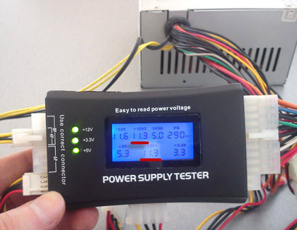
Pay attention to the highlighted areas. We see that the voltage of the computer's power supply along lines 12V1 and 12V2 is 11.3 V (at a nominal value of 12V).
Is it good or bad? You ask:) I answer: according to the standard, there are clearly defined limits of acceptable values that are considered “normal”. Everything that doesn’t fit into them sometimes works great, but often it’s buggy or doesn’t turn on at all :)
For clarity, here is a table of the permissible voltage spread:

The first column shows us all the main lines that are in the power supply. Column " Tolerance"this is the maximum permissible deviation from the norm (in percentage). According to it, in the field" min" indicates the minimum permissible value along this line. Column " nom" gives the nominal (recommended indicator, according to the standard). And - " Max" - maximum permissible.
As you can see, (in one of the previous photographs) our measurement result along lines 12V1 and 12V1 is 11.30V and it does not fit into the standard five percent spread (from 11.40 to 12.60V). This malfunction of the power supply, apparently, leads to the fact that it starts at all or the third time.
So, we have discovered a suspicious malfunction. But how can you carry out an additional check and make sure that the problem is precisely the low voltage +12V? Using our (most common) multimeter under the brand " XL830L».
How to test a power supply using a multimeter?
We will start the block as described in, closing two contacts (pins) with a paper clip or a piece of wire of a suitable diameter.

Now - we connect an external fan to the power supply (remember about the “load”) and - a 220V cable. If we did everything correctly, the external fan and the “Carlson” on the unit itself will begin to rotate. The picture at this stage looks like this:

The photo shows the devices with which we will check the power supply. We already looked at the work of the tester from the Middle Kingdom at the beginning of the article, now we will make the same measurements, but with the help.
Here you need to digress a little and take a closer look at the computer’s power supply connector itself. More precisely, the voltages that are present in it. As we can see (in one of the previous photos) it consists of 20 (or 24 four) wires of different colors.
These colors are used for a reason, but mean very specific things:
- Black the color is “ground” (COM, aka common wire or ground)
- Yellow color + 12V
- Red: +5V
- Orange color: +3.3V
I suggest checking and considering each pin separately:

This is much clearer, isn’t it? You remember about colors, right? (black, yellow, red and orange). This is the main thing we need to remember and understand before checking the power supply ourselves. But there are a few more pins that we need to pay attention to.
First of all, these are the wires:
- Green PS-ON - when it is shorted to ground, the power supply starts up. In the diagram this is shown as “PSU On”. It is these two contacts that we close with a paper clip. The voltage on it should be 5V.
- Next - gray and the “Power Good” or “Power OK” signal transmitted through it. Also 5V (see note)
- Immediately behind it is a purple one marked 5VSB (5V Standby). This is five volts of standby voltage ( duty room). It is supplied to the computer even when it is turned off (the 220V cable must, of course, be connected). This is necessary, for example, in order to be able to send a command to a remote computer over the network to launch “Wake On Lan”.
- White (minus five volts) - now practically not used. Previously, it served to provide current to expansion cards installed in the ISA slot.
- Blue (minus twelve Volts) - currently consumed by the “RS232” (COM port), “FireWire” and some PCI expansion cards.
Before checking the power supply with a multimeter, let’s look at two more of its connectors: an additional 4-pin for the needs of the processor and a “Molex” connector for connecting optical drives.

Here we see the colors already familiar to us (yellow, red and black) and their corresponding values: + 12 and + 5V.
For greater clarity, download all power supply voltages in a separate archive.
Now let’s make sure that the theoretical knowledge we have received is fully confirmed in practice. How? I suggest starting with a careful study of the factory “sticker” (sticker) on one of the real ATX power supplies.

Pay attention to what is underlined in red. "DC OUTPUT" (Direct Current Output - DC output value).
- +5V=30A (RED) - plus five IN, provides a current of 30 Amperes (red wire) We remember from the text above that we receive exactly +5V along the red wire?
- +12V=10A (YELLOW) - plus twelve IN we have a current of ten amperes (its wire is yellow)
- +3.3V=20A (ORANGE) - three point three line IN can withstand twenty amps of current (orange)
- -5V (WHITE) - minus five IN- similar to described above (white)
- -12V (BLUE) - minus twelve IN(blue)
- +5Vsb (PURPLE) - plus five IN standby. We have already talked about it above (it is purple).
- PG (GRAY) - Power Good signal (gray).
On a note: if, for example, the standby voltage according to measurements is not five volts, but, say, four, then it is very likely that we are dealing with a problematic voltage stabilizer (zener diode), which should be replaced with a similar one.
And the last entry from the list above tells us that the maximum output power of the product in watts is 400W, and only the 3 and 5V channels can provide a total of 195 watts.
Note: « "Power Good"- “nutrition is normal.” A voltage of 3 to 6 Volts (nominal 5V) is generated after the necessary internal checks through 100 - 500 ms(milliseconds, it turns out - from 0.1 to 0.5 seconds) after switching on. After this, the clock generator chip generates an initial setting signal. If it is missing, then another signal appears on the motherboard - a CPU hardware reset, preventing the computer from working with abnormal or unstable power.
If the output voltage does not correspond to the nominal voltage (for example, when it decreases in the mains), the “Power Good” signal disappears and the processor automatically restarts. When all required current values “P.G.” are restored is formed anew and the computer starts working as if it had just been turned on. Thanks to the quick turn off of the “Power Good” signal, the PC “does not notice” problems in the power system, since it stops operation before errors and other problems associated with its instability may appear.
In a properly designed unit, the issuance of the “Power Good” command is delayed until the power supply in all circuits is stabilized. In cheap power supplies, this delay is insufficient and the processor starts working too early, which, in itself, can even lead to corruption of the contents of the CMOS memory.
Now, armed with the necessary theoretical knowledge, we understand how to properly check a computer’s power supply using a multitester. We set the measurement limit on the DC scale to 20 Volts and begin checking the power supply.
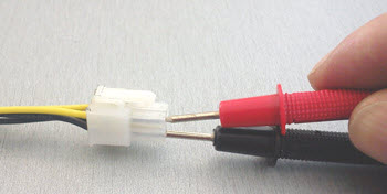
We apply the black “probe” of the tester to the black “ground” wire, and start “poking” with the red one into all the remaining ones :)
Notes e: don’t worry, even if you start “feeling” for something wrong, you won’t burn anything - you’ll just get incorrect measurement results.
So, what do we see on the multimeter screen when checking the power supply?

On the +12V line the voltage is 11.37V. Remember, the Chinese tester showed us 11.3 (in principle, a similar value). But it still does not reach the minimum permissible of 11.40V.
Also pay attention to two useful buttons on the tester: “Hold” - holding measurement readings on the display and “Back Light” - backlighting the screen (when working in poorly lit rooms).

We see the same (not inspiring) 11.37V.
Now (for the sake of completeness) we need to check the power supply to make sure it meets the other ratings. Let's test, for example, five Volts on the same Molex.

The black “probe” is to “ground”, and the red one is to the red five-volt pin. Here is the result on the multimeter:

As we can see, the indicators are normal. Similarly, we measure all other wires and compare each result with the nominal value from.
Thus, checking the power supply showed that the device has a greatly underestimated (relative to the nominal) voltage of +12V. Let's, for clarity, once again measure the same line (yellow color on the additional 4-pin connector) on a fully operational device.

We see - 11.92V (remember that the minimum permissible value here is 11.40V). This means we are well within the tolerance.
But checking the computer's power supply is only half the battle. After this, it also needs to be repaired, and we discussed this point in one of the previous articles, which was called.
I hope that now you yourself, if necessary, will be able to check the computer’s power supply, you will know exactly what voltages should be present at its terminals and act in accordance with this.
Updated: 02/06/2023
103583
If you notice an error, select a piece of text and press Ctrl+Enter


