The paper maps of the area were replaced by electronic maps, navigation on which is carried out using the GPS satellite system. From this article you will learn when satellite navigation appeared, what it is now and what awaits it in the near future.
During World War II, the flotillas of the United States and Great Britain had a significant trump card - the LORAN navigation system using radio beacons. At the end of hostilities, the technology was put at their disposal by civilian ships of "pro-Western" countries. A decade later, the USSR put its answer into operation - the Chaika navigation system, based on radio beacons, is still in use today.
But terrestrial navigation has significant drawbacks: uneven terrain becomes an obstacle, and the influence of the ionosphere negatively affects the signal transmission time. If there is too much distance between the navigation beacon and the ship, the position error can be measured in kilometers, which is unacceptable.
Ground-based beacons were replaced by satellite navigation systems for military purposes, the first of which, the American Transit (another name for NAVSAT), was launched in 1964. Six low-orbit satellites ensured the accuracy of determining the coordinates up to two hundred meters.
In 1976, the USSR launched a similar military navigation system, Cyclone, and three years later, a civilian one called Cicada. A big disadvantage of early satellite navigation systems was that they could only be used for a short time, like an hour. Low orbit satellites, and even in small numbers, were not able to provide a wide signal coverage.
In 1974, the US Army launched the first satellite of the then-new NAVSTAR navigation system, which was later renamed GPS (Global Positioning System), into orbit. In the mid-1980s, civilian ships and aircraft were allowed to use GPS technology, but for a long time they were able to position at times less accurate than the military. The twenty-fourth GPS satellite, the last required to cover the Earth's surface, was launched in 1993.
In 1982, the USSR presented its answer - it became the GLONASS (Global Navigation Satellite System) technology. The final 24th GLONASS satellite went into orbit in 1995, but the short service life of the satellites (three to five years) and insufficient funding for the project put the system out of action for almost a decade. It was only in 2010 that GLONASS global coverage was restored.

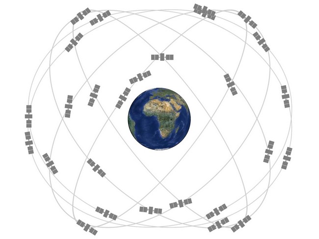
To avoid such failures, both GPS and GLONASS now use 31 satellites: 24 main and 7 backup, as they say, just in case of a "fire" case. Modern navigation satellites fly at an altitude of about 20 thousand km and manage to circle the Earth twice in a day.
Positioning in the GPS network is carried out by measuring the distance from the receiver to several satellites, the location of which is precisely known at the current time. The distance to a satellite is measured by multiplying the signal delay by the speed of light.
Communication with the first satellite provides information only about the sphere of possible receiver locations. The intersection of two spheres will give a circle, three - two points, and four - the only true point on the map. In the role of one of the spheres, our planet is most often used, which allows instead of four satellites to be positioned only on three. In theory, GPS positioning accuracy can reach 2 meters (in practice, the error is much larger).

Each satellite sends a large set of information to the receiver: exact time and its correction, almanac, ephemeris data and ionospheric parameters. A precise time signal is required to measure the delay between its sending and receiving.
Navigation satellites are equipped with high-precision cesium clocks, while receivers are equipped with much less accurate quartz ones. Therefore, to check the time, contact is made with an additional (fourth) satellite.

But cesium clocks can also be wrong, so they are compared with hydrogen clocks placed on the ground. For each satellite in the control center of the navigation system, a time correction is individually calculated, which is subsequently sent to the receiver along with the exact time.
Another important component of the satellite navigation system is the almanac, which is a table of satellite orbit parameters for a month ahead. The almanac, as well as the time correction, are calculated in the control center.

Satellites and individual ephemeris data are transmitted, on the basis of which orbit deviations are calculated. And given that the speed of light is not constant anywhere except in vacuum, the signal delay in the ionosphere is necessarily taken into account.
Data transmission in the GPS network is carried out strictly at two frequencies: 1575.42 MHz and 1224.60 MHz. Different satellites broadcast on the same frequency but use CDMA code division. That is, the satellite signal is just noise, which can only be decoded if there is an appropriate PRN code.

The above approach makes it possible to provide high noise immunity and use a narrow frequency range. However, sometimes GPS receivers still have to search for satellites for a long time, due to a number of reasons.
Firstly, the receiver initially does not know where the satellite is, whether it is moving away or approaching, and what is the frequency offset of its signal. Secondly, contact with a satellite is considered successful only when a complete set of information is received from it. The speed of data transfer in the GPS network rarely exceeds 50 bps. And as soon as the signal breaks off due to radio interference, the search begins anew.

Now GPS and GLONASS are widely used for peaceful purposes and, in fact, are interchangeable. The latest navigation chips support both communication standards and connect to the satellites that are found first.
American GPS and Russian GLONASS are far from the only satellite navigation systems in the world. For example, China, India and Japan have begun deploying their own SSNs called BeiDou, IRNSS and QZSS respectively, which will operate only within their countries and therefore require a relatively small number of satellites.
But the biggest interest, perhaps, is the Galileo project, which is being developed by the European Union and should be launched at full capacity before 2020. Initially, Galileo was conceived as a purely European network, but the countries of the Middle East and South America have already declared their desire to participate in its creation. So, a “third force” may soon appear on the market of global CLOs. If this system is also compatible with existing ones, and most likely it will be, consumers will only benefit - the speed of searching for satellites and positioning accuracy should grow.
Navigation is the definition of coordinate-time parameters of objects.
The first effective means of navigation was positioning by visible celestial bodies (sun, stars, moon). Another simplest method of navigation is georeferencing, ie. positioning relative to known landmarks (water towers, power lines, highways and railways, etc.).
Navigation and positioning systems are designed to constantly monitor the location (state) of objects. Currently, there are two classes of navigation and positioning aids: terrestrial and space.
Ground-based include stationary, portable and portable systems, complexes, ground reconnaissance stations, other means of navigation and positioning. The principle of their operation is to control the radio air by means of special antennas connected to scanning radio stations, and to isolate radio signals emitted by radio transmitters of tracking objects or emitted by the complex (station) itself and reflected from the tracking object or from a special tag or on-board code sensor (CBD) placed on object. When using this kind of technical means, it is possible to obtain information about the coordinates of the location, direction and speed of movement of the controlled object. If there is a special mark or CBD on the tracking objects, identification devices connected to the systems allow not only marking the location of monitored objects on an electronic map, but also distinguishing them accordingly.
Space navigation and positioning systems are divided into two types.
The first type of space navigation and positioning systems is distinguished by the use of special sensors on mobile tracking objects - satellite navigation system receivers such as GLONASS (Russia) or GPS (USA). Navigation receivers of mobile tracking objects receive a radio signal from the navigation system, which contains the coordinates (ephemeris) of the satellites in orbit and the time reference. The processor of the navigation receiver, according to data from satellites (at least three), calculates the geographical latitude and longitude of its location (receiver). This information (geographical coordinates) can be visualized both on the navigation receiver itself, in the presence of an information output device (display, monitor), and at the tracking point, when it is transmitted from the navigation receiver of a moving object via radio communication (radial, conventional, trunking, cellular , satellite).
The second type of space navigation and positioning systems is distinguished by scanning reception (bearing) in orbit of signals coming from radio beacons installed on the tracking object. A satellite receiving signals from radio beacons, as a rule, first accumulates, and then at a certain point in the orbit transmits information about tracking objects to a ground data processing center. At the same time, the information delivery time is somewhat increased.
Satellite navigation systems allow:
At present, the functions of specialized navigation and positioning systems (automatic tracking of the current location of subscriber units, communication terminals in order to provide roaming and provide communication services) can be performed with relative accuracy by satellite and cellular (if the base stations have positioning equipment) radio communication systems.
The widespread introduction of navigation and positioning systems, the widespread installation of appropriate equipment in Russian cellular networks in order to determine and constantly monitor the location of operating transmitters, patrols, vehicles, and other objects of interest to law enforcement agencies, could significantly expand the possibilities of law enforcement.
The basic principle of positioning using satellite navigation systems is the use of satellites as reference points.
In order to determine the latitude and longitude of a terrestrial receiver, the receiver must receive signals from at least three satellites and know their coordinates and the distance from the satellites to the receiver (Fig. 6.8). The coordinates are measured relative to the center of the earth, which has the coordinate (0, 0, 0).
The distance from the satellite to the receiver is calculated from the measured signal propagation time. These calculations are not difficult to perform, since it is known that electromagnetic waves propagate at the speed of light. If the coordinates of three satellites and the distances from them to the receiver are known, then the receiver can calculate one of two possible places in space (points 1 and 2 in Fig. 6.8). Typically, the receiver can determine which of the two points is valid, since one location value has a meaningless value.
Rice. 6.8. Position determination by signals from three satellites
In practice, to eliminate the generator clock error, which affects the accuracy of time difference measurements, it is necessary to know the location and distance to the fourth satellite (Fig. 6.9).
Rice. 6.9. Position determination by signals from four satellites
Currently, there are two satellite navigation systems - GLONASS and GPS - that are actively used.
Satellite navigation systems include three components (Fig. 6.10):
Rice. 6.10. Composition of satellite navigation systems
The space segment of the GLONASS system consists of 24 navigation spacecraft (NSV) located in circular orbits with a height of 19,100 km, an inclination of 64.5 ° and an orbital period of 11 h 15 min in three orbital planes (Fig. 6.11). Each orbital plane accommodates 8 satellites with a uniform latitude shift of 45°.
The space segment of the GPS navigation system consists of 24 main satellites and 3 reserve ones. The satellites are in six circular orbits with an altitude of about 20,000 km, an inclination of 55°, evenly spaced in longitude at 60° intervals.
Rice. 6.11. Orbits of GLONASS and GPS satellites
The segment of the ground control complex of the GLONASS system performs the following functions:
To synchronize the time scales of various satellites with the required accuracy, cesium frequency standards with a relative instability of the order of 10 -13 s are used on board the NSC. The ground control complex uses a hydrogen standard with a relative instability of 10 -14 s. In addition, the GCC includes means for correcting satellite time scales relative to the reference scale with an error of 3-5 ns.
The ground segment provides ephemeris support for the satellites. This means that the parameters of satellite movement are determined on the ground and the values of these parameters are predicted for a predetermined period of time. The parameters and their forecast are embedded in the navigation message transmitted by the satellite along with the transmission of the navigation signal. This also includes time-frequency corrections of the satellite's onboard time scale relative to system time. Measurement and prediction of the motion parameters of the satellite are carried out in the Ballistic Center of the system based on the results of trajectory measurements of the distance to the satellite and its radial velocity.
The system user equipment is a radio engineering device designed to receive and process radio navigation signals of navigation spacecraft to determine spatial coordinates, components of the motion velocity vector and correct the time scales of the user of the global navigation satellite system.
The receiver determines the location of the consumer, which selects from all the observed satellites the most favorable in terms of ensuring navigation accuracy. According to the ranges to the selected satellites, it determines the longitude, latitude and height of the consumer, as well as the parameters of its movement: direction and speed. The received data is displayed on the display in the form of digital coordinates, or displayed on a map previously copied to the receiver.
Receivers of satellite navigation systems are passive, i.e. they do not emit signals and do not have a reverse communication channel. This allows you to have an unlimited number of consumers of navigation communication systems.
Currently, systems for monitoring the movement of objects based on satellite navigation systems have become widespread. The structure of such a system is shown in fig. 6.12.
Rice. 6.12. Structure of the monitoring system
Navigation receivers installed on the tracking objects receive signals from satellites and calculate their coordinates. But, since navigation receivers are passive devices, it is necessary to provide a system for transmitting the calculated coordinates to the monitoring center in the system. VHF radio modems, GSM/GPRS/EDGE modems (2G networks), third-generation networks operating on the UMTS/HSDPA protocols, CDMA modems, satellite communication systems, etc. can serve as means of transmitting data on the coordinates of the object of observation.
The monitoring center of a satellite navigation and monitoring system is designed to monitor objects on which navigation and communication equipment is installed (contained) in order to control its individual parameters (location, speed, direction of movement) and make decisions on certain actions.
The monitoring center contains software and hardware information processing tools that provide:
The navigation and monitoring system of the internal affairs bodies solves the following tasks:
To ensure high reliability and reliability of the transmission of monitoring information from the on-board equipment of motor vehicles of the units of the Ministry of Internal Affairs of Russia to the guards on duty, it is necessary to use a backup data transmission channel as part of the system, which can be used as
Determining your location, both on land and at sea, in a forest or in a city, is an issue that is as relevant today as it has been over the past centuries. The era of the discovery of radio waves greatly simplified the task of navigation and opened up new prospects for humanity in many areas of life and activity, and with the discovery of the possibility of conquering outer space, a huge breakthrough was made in the field of determining the coordinates of the location of an object on Earth. To determine the coordinates, a satellite navigation system is used, which receives the necessary information from satellites located in orbit.
Now there are two global coordinate systems in the world - the Russian GLONASS and the American NavStar, better known as GPS (an abbreviation for the name Global Position System - global positioning system).
The GLONASS satellite navigation system was invented in the Soviet Union in the early 80s of the last century and the first tests took place in 1982. It was developed by order of the Ministry of Defense and was specialized for operational global navigation of ground moving objects.
The American GPS navigation system is similar in structure, purpose and functionality to GLONASS and was also developed by order of the United States Department of Defense. It has the ability to determine with high accuracy both the coordinates of a ground object, and to carry out time and speed binding. NavStar has 24 navigation satellites in orbit, providing a continuous navigation field over the entire surface of the Earth.
The receiver indicator of the satellite navigation system (GPS-navigator or) receives signals from satellites, measures the distances to them, and, using the measured ranges, solves the problem of determining its coordinates - latitude, longitude and, when receiving signals from 4 or more satellites - altitude above sea level , speed, direction (course), distance traveled. The navigator includes a receiver for receiving signals, a computer for their processing and navigation calculations, a display for displaying navigation and service information, and a keyboard for controlling the operation of the device.
These receivers are designed for permanent installation in wheelhouses and dashboards. Their main features are: the presence of a remote antenna and power supply from an external DC source. They have, as a rule, large liquid-crystal monochrome screens with alphanumeric and graphic display of information.
Compact waterproof high performance GPS/DGPS/WAAS receiver designed for small boats. This GPS receiver from the company is capable of receiving and processing additional DGPS/WAAS differential correction signals. This feature allows, when receiving corrections from a beacon or geostationary WAAS satellites, to use an accuracy better than 5 meters.
New (D)GPS navigator with built-in differential correction receiver. Path-laying technology allows precise creation of long-range routes. It is possible to select loxodromic heading (RL) for short distances and orthodromic heading (GC) for long distances.
With pathfinding technology, it can accurately create high-range routes. It is possible to select loxodromic heading (RL) for short distances and orthodromic heading (GC) for long distances.
Fixed receivers have a wide range of functionality, especially professional instruments for marine use. They have a large amount of memory, the ability to solve various navigational tasks, and their interface provides the ability to be included in the ship's navigation system.
This is a modern GLONASS/GPS navigation satellite receiver designed for all types of ships.
Developed by specialists of the company "Radio Complex" using the latest achievements in the field of marine navigation. RK-2006 has the ability to receive signals from already deployed satellite constellations, such as GLONASS and GPS, but also from promising European and Asian positioning systems, this allows, with increased noise immunity and protection from the failure of any system, to determine the coordinates of the vessel and its course and speed.
The receiver of global navigation satellite systems GPS and GLONASS, from the South Korean manufacturer of marine radio navigation equipment Samyung ENC Co., Ltd - SGN-500.
When using GLONASS and GPS in combined receivers (almost all GLONASS receivers are combined), the accuracy of determining the coordinates is almost always “excellent” due to the large number of visible satellites and their good relative position.
Displaying navigation information
GLONASS/GPS receivers use two ways of displaying information: alphanumeric and graphic (sometimes the term "pseudographic" is used).
The alphanumeric method for displaying the information received uses:
The graphic display method is carried out with the help of drawings formed on the screen, representing the nature of the movement of the carrier (ship, car, person). The graphics in the devices of different companies are almost the same and differ, as a rule, in details. The most common drawings are:
Location accuracy
The accuracy of determining the coordinates of a place is a fundamental indicator of any navigation system, the value of which will determine how correctly the ship will follow the route laid out and whether it will fall on nearby shoals or stones.
The accuracy of instruments is usually estimated by the value of the root-mean-square error (RMS) - the interval in which 72% of the measurements fall, or by the maximum error corresponding to 95%. Most manufacturers estimate the RMS of their GPS receivers at 25 meters, which corresponds to a maximum error of 50 meters.
Navigation performance
The navigation capabilities of GLONASS/GPS receivers are characterized by the number of waypoints, routes and waypoints contained in them that are memorized by the instrument. Waypoints are understood as characteristic points on the surface used for navigation. Modern ones can create and store, depending on the model, from 500 to 5000 waypoints and 20-50 routes with 20-30 points in each.
In addition to waypoints, any receiver has a reserve of points for recording and saving the route traveled. This number can reach from 1000 to several tens of thousands of points in professional navigators. The recorded track can be used to return along it.
Number of simultaneously tracked satellites
This indicator characterizes the stability of the navigator and its ability to provide the highest accuracy. Given the fact that to determine the two coordinates of the position - longitude and latitude - you need to simultaneously track 3 satellites, and to determine the height - four. Modern GLONASS / GPS navigators, even portable ones, have 8 or 12-channel receivers capable of simultaneously receiving and tracking signals from up to 8 or 12 satellites, respectively.
Keywords: distance to the object; clock synchronization; satellite and receiver clock error; ephemeris.
As a result of studying the material of the second chapter, the student must:
know
be able to
own
The basic principle underlying the satellite navigation system is simple and has long been used for navigation and orientation: if the location of a reference point and the distance to it are known, then you can draw a circle (in a three-dimensional case, a sphere) on which a point should be located receiver location.
The principle of determining the coordinates of an object in the GNSS system is based on calculating the distance from it to several satellites, the exact coordinates of which are known. Information about the distance of at least three satellites allows you to determine the coordinates of the object as the point of intersection of spheres, the center of which is the satellites, and the radius is the measured distance to each of the satellites (Fig. 2.1). The idea behind measuring the distance to satellites
Satellite 1
Sputnik 2
Object location
Sputnik 3
Rice. 2.1.The simplest case of satellite navigation
nick, is based on the well-known equality: distance is speed multiplied by the time of movement.
Let's imagine that, while in a car, we want to determine our location on a long and straight street. Suppose there is a radio transmitter at the end of the street that sends out a clock pulse every second. The car has a clock that is synchronized with the radio transmitter's clock. By measuring the travel time of the pulse from the transmitter to the car, we can determine the position of the car on the street (Fig. 2.2).
transmitted signal
received signal

Distance th
Rice. 2.2.Determination of distance by time and speed
signal propagation
Since the clock synchronization in the car with the transmitter is not perfect, there is a difference between the calculated distance and the actual distance. In navigation, this incorrect value is called pseudorange. If the time error is one microsecond (1 µs), then, taking into account the speed of propagation of radio waves, the error will be 300 m.
It would be possible to solve this problem by equipping the car with an atomic clock, but this will significantly affect the budget. Another solution would be to use a second synchronized transmitter whose distance is known. By measuring both propagation times, the distance can be accurately determined despite the inaccurate onboard clock (Figure 2.3). To accurately calculate the position and time along the line (assuming the line continues in only one direction), we need to use two time transmitters. Let us show that the distance /) in this case is calculated by the formula
where At, Dt 2 - the time of arrival of the signal measured by the car on-board clock, respectively, from the first and second transmitters; With - the speed of light; A- distance between transmitters.
According to the first and second measurements, the pseudoranges D and D are determined by the expressions
D = ABOUT+ 5s; (2.2)
D \u003d (L-D + 5s, (2.3)
where 5 is the error of the car's clock in seconds.
Obviously, if the car's clock is in a hurry, then sign 5 is positive, if it is behind, then sign 5 is negative.
Replacing the pseudoranges D and D in equalities (2.2), (2.3) by their expressions in terms of the speed of light and the measured signal arrival time (respectively, D = C Dt, G>2 = with - Dm 2) and after performing obvious transformations, we arrive at expression (2.1).
From the above reasoning, we can conclude the following: with an unsynchronized onboard clock used in position calculation, it is necessary to use the number of time signal transmitters that exceeds the number of unknown measurements per unit.

Rice. 2.3.
despite timing errors
The navigation receiver measures the time it takes for a radio signal to travel from a satellite to an object, and then calculates the distance from that time.
Radio waves propagate at the speed of light - 300,000 km/s. If you accurately determine the time at which the satellite began to send its radio signal, and the time when it was received, it is not difficult to determine the propagation time of the radio signal. Multiplying the signal propagation speed by the time in seconds, we get the distance to the satellite.
Ground clocks must be very accurate, as light travels extremely fast. For example, if a GPS satellite were directly overhead, it would take only about 65 ms for the radio signal to travel from the satellite to the ground receiver (Figure 2.4).
The global navigation satellite system is built using a time measurement method based on an atomic frequency standard. Relative instability of the frequency standard of the onboard synchronizing device of the GLONASS navigation satellite (1-5) 10 -13 s per day.
The main difficulty in measuring the transit time of a radio signal is the exact selection of the time at which the signal was transmitted from the satellite. To do this, GNSS developers turned to the following idea: to synchronize satellites and receivers so that they generate the same code at exactly the same time. In other words, the receiver generates its
Satellite clock readings Satellite clock readings
and receiver 0 ms and receiver 65 ms

Signal transmission time (start time)
Signal reception time (Stop time)
1_ Signal
Rice. 2.4.Signal transit time determination
internal code at the same time as the satellite transmitter, i.e. ideally, it should exactly duplicate the satellite code.
Then it remains to receive the code from the satellite and see how long ago the receiver generated the same code. To do this, the receiver compares the time difference between the reception of the corresponding part of the satellite code with the same part of its own code. The shift of one code revealed in this way with respect to another will correspond to the time it takes the signal to travel the distance from the satellite to the receiver. Knowing the time shift and the speed of propagation of radio waves, the receiver obtains the distance to the satellite, called the pseudorange.
The advantage of using code packets (code sequences) is that time shift measurements can be taken at any time.
The GNSS system uses a method of determining the position by range to satellite landmarks, which are located using a pseudo-random code. Both satellites and receivers generate very complex digital code sequences. Codes are complicated on purpose so that they can be reliably and unambiguously compared, and also for some other reasons. Either way, the codes are so complex that they look like a long series of random pulses. In reality, they are carefully selected "pseudo-random sequences" that repeat every millisecond.
Yatsenkov V.S. Basics of satellite navigation
Systematized information about satellite navigation systems GPS NAVSTAR and GLONASS. The history of the development and creation of systems is outlined, the basic principles of their work are considered. The characteristics and structure of navigation signals, data on the technical capabilities and parameters of existing systems are given, definitions of basic concepts and terms are given, and the most informative Internet resources are listed.
For developers and users of navigation systems of various levels of training, from amateurs who use GPS receivers at home to professionals who use navigation tools in their daily work. It may be useful for students of radio engineering specialties and graduate students.
Screenshots: table of contents
Add. information : ---
My distributions of literature on GEO-sciences (Geodesy, Cartography, Land management, GIS, remote sensing, etc.)
Geodesy and Satellite Positioning Systems
- “Saying THANK YOU extends the life of the torrent” (Dark_Ambient )


