Household devices are sensitive to power surges, wear out faster, and malfunctions appear. In the electrical network, the voltage often changes, decreases or increases. This is due to the remoteness of the energy source and poor quality power line.
To connect devices to a stable power supply, voltage stabilizers are used in residential premises. At its output, the voltage has stable properties. The stabilizer can be purchased at a retail chain, but such a device can be made with your own hands.
There are tolerances for voltage changes of no more than 10% of the nominal value (220 V). This deviation must be observed both upward and downward. But there is no ideal electrical network, and the voltage in the network often changes, thereby aggravating the operation of devices connected to it.
Electrical appliances react negatively to such vagaries of the network and can quickly fail, losing their intended functions. To avoid such consequences, people use homemade devices called voltage stabilizers. A device made using triacs has become an effective stabilizer. We will look at how to make a voltage stabilizer with your own hands.
This stabilization device will not have increased sensitivity to changes in voltage supplied through the common line. Voltage smoothing will be carried out if the input voltage is in the range from 130 to 270 volts.
Devices connected to the network will be powered by a voltage ranging from 205 to 230 volts. From such a device it will be possible to power electrical devices with a total power of up to 6 kW. The stabilizer will switch the consumer load in 10 ms.
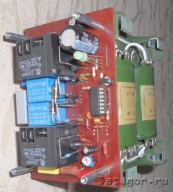
Stabilization device diagram.
The voltage stabilizer according to the specified circuit includes the following parts:
Let's look at how it works.
After connecting the power, capacitance C1 is in a discharge state, transistor VT1 is open, and VT2 is closed. VT3 transistor also remains closed. Through it, current flows to all LEDs and an optitron based on triacs.
Since this transistor is in a closed state, the LEDs do not light up, and each triac is closed, the load is turned off. At this moment, current flows through resistance R1 and arrives at C1. Then the capacitor begins to charge.
The shutter speed range is three seconds. During this period, all transition processes are carried out. After their completion, a Schmitt trigger based on transistors VT1 and VT2 is triggered. After this, the 3rd transistor opens and the load is connected.
The voltage coming from the 3rd winding T1 is equalized by diode VD2 and capacitance C2. Next, the current flows to the divider at resistances R13-14. From resistance R14, a voltage, the magnitude of which directly depends on the magnitude of the voltage, is included in each non-inverting comparator input.
The number of comparators becomes equal to 8. They are all made on DA2 and DA3 microcircuits. At the same time, direct current is supplied to the inverted input of the comparators, supplied using dividers R15-23. Next, the controller comes into action, receiving the input signal of each comparator.
When the input voltage drops below 130 volts, a small logic level appears at the outputs of the comparators. At this moment, transistor VT4 is open, the first LED is blinking. This indication indicates the presence of low voltage, which means that the adjustable stabilizer cannot perform its functions.
All triacs are closed and the load is turned off. When the voltage is in the range of 130-150 volts, then signals 1 and A have the properties of a high logic level. This level is low. In this case, transistor VT5 opens and the second LED begins to signal.
Optosimistor U1.2 opens, just like triac VS2. The load current will flow through the triac. Then the load will enter the upper terminal of the autotransformer coil T2.
If the input voltage is 150 - 170 V, then signals 2, 1 and B have an increased logical level value. Other signals are low. At this input voltage, transistor VT6 opens and the 3rd LED turns on. At this moment, the 2nd triac opens and current flows to the second terminal of the T2 coil, which is 2nd from the top.
A self-assembled 220-volt voltage stabilizer will connect the windings of the 2nd transformer if the input voltage level reaches, respectively: 190, 210, 230, 250 volts. To make such a stabilizer, you need a 115 x 90 mm printed circuit board made of foil fiberglass.

The board image can be printed on a printer. Then, using an iron, this image is transferred to the board.
You can make transformers T1 and T2 yourself. For T1, whose power is 3 kW, it is necessary to use a magnetic core with a cross section of 1.87 cm 2, and 3 PEV wires - 2. 1st wire with a diameter of 0.064 mm. The first coil is wound with it, with a number of turns of 8669. The other 2 wires are used to form the remaining windings. The wires on them must be of the same diameter 0.185 mm, with the number of turns 522.
In order not to make such transformers yourself, you can use ready-made versions of TPK - 2 - 2 x 12 V, connected in series.

To make a 6 kW transformer T2, a toroidal magnetic core is used. The winding is wound with PEV-2 wire with the number of turns 455. 7 taps must be installed on the transformer. The first 3 of them are wound with 3 mm wire. The remaining 4 branches are wound with tires with a cross section of 18 mm 2. With such a wire cross-section, the transformer will not heat up.
The taps are made on the following turns: 203, 232, 266, 305, 348 and 398. The turns are counted from the bottom tap. In this case, the electric current of the network must flow through tap 266 turns.
The remaining elements and parts of the stabilizer for self-assembly are purchased in the retail chain. Here is a list of them:
Optocouplers MOS 3041 are replaced with MOS 3061. KR 1158 EN 6A stabilizer can be replaced with KP 1158 EN 6B. The comparator K 1401 CA 1 can be installed as an analogue of LM 339 N. Instead of diodes, KTs 407 A can be used.
The KR 1158 EN 6A microcircuit must be installed on the heat sink. For its manufacture, an aluminum plate of 15 cm 2 is used. It is also necessary to install triacs on it. For triacs it is allowed to use a common heat sink. The surface area must exceed 1600 cm2. The stabilizer must be equipped with a KR 1554 LP 5 microcircuit, which acts as a microcontroller. Nine LEDs are arranged so that they fit into the holes on the front of the instrument panel.
If the housing design does not allow them to be installed in the same way as in the diagram, then they are placed on the other side where the printed tracks are located. LEDs must be installed as a flashing type, but non-blinking diodes can also be installed, provided that they glow bright red. For such purposes, use AL 307 KM or L 1543 SRC - E.
You can assemble simpler versions of the devices, but they will have certain features.
If we list the advantages of stabilizers made independently, the main advantage is low cost. Manufacturers of devices often inflate prices, and in any case, their own assembly will cost less.
Another advantage can be determined by such a factor as the ability to easily repair the device with your own hands. After all, who, if not you, knows better about a device assembled with your own hands.
In the event of a breakdown, the owner of the device will immediately find the faulty element and replace it with a new one. Easy replacement of parts is created by the fact that all parts were purchased in a store, so they can be easily purchased again at any store.
The disadvantage of a self-assembled voltage stabilizer is its complex configuration.
Let's look at how you can make your own 220-volt stabilizer with your own hands, having a few simple parts on hand. If the voltage in your electrical network is significantly reduced, then such a device will come in handy. To make it, you will need a ready-made transformer and a few simple parts. It is better to take note of such an example of a device, since it turns out to be a good device with sufficient power, for example, for a microwave.
For refrigerators and various other household devices, a decrease in network voltage is very harmful, more than an increase. If you increase the network voltage using an autotransformer, then while the network voltage decreases, the voltage at the device output will be normal. And if the voltage in the network becomes normal, then at the output we will get an increased voltage value. For example, let’s take a 24 V transformer. With a line voltage of 190 V, the output of the device will be 210 V; with a network value of 220 V, the output will be 244 V. This is quite acceptable and normal for the operation of household devices.

For manufacturing we need the main part - this is a simple transformer, but not an electronic one. You can find it ready-made, or you can change the data on an existing transformer, for example, from a broken TV. We will connect the transformer according to the autotransformer circuit. The output voltage will be approximately 11% higher than the mains voltage.
In this case, you need to be careful, since during a significant voltage drop in the network upward, the output of the device will produce a voltage that significantly exceeds the permissible value.
The autotransformer will add only 11% to the line voltage. This means that the power of the autotransformer is also taken at 11% of the consumer’s power. For example, the power of a microwave oven is 700 W, which means we take a transformer of 80 W. But it is better to take power with a reserve.
The SA1 regulator makes it possible, if necessary, to connect the consumer load without an autotransformer. Of course, this is not a full-fledged stabilizer, but its production does not require large investments and a lot of time.
Hello, dear readers of the site http://zametkielectrika.ru.
The topic of today's article relates to such currently integral devices as voltage stabilizers for the home. Now I will explain to you why they are integral. The energy supply organization does not pay due attention to the quality of electricity supplied to consumers. The reason for this may be the lack of laws and the imposition of sanctions for inadequate quality. In addition, do not forget that the energy supply organization is a monopolist in the supply of electrical energy.
The supplied electricity is a commodity. And if this “product” is not of adequate quality, it can lead to failure of electrical equipment. Therefore, each consumer must take care of himself by using home voltage stabilizers, which are designed to maintain a stable supply voltage for household and industrial loads.
To do this, let us turn to the following regulatory documents, which regulate the parameters of the electrical network from the power source to the consumer.


These GOSTs provide a breakdown of the parameters and digital indicators of the quality of electrical energy, methods for measuring them, the causes and probabilities of the occurrence of one or another quality deviation.

By the way, you can download PUE 7th edition from my website.
Now let's look at the main indicators of the quality of electrical energy, according to GOST 13109-97.
1. Voltage deviation
The following deviation standards exist:
According to GOST 21128-83, the nominal effective voltage of a single-phase household network should be 220 (V). It follows that the voltage limit from 209 - 231 (V) is a normal permissible deviation, and the voltage limit from 198 - 242 (V) is the maximum permissible deviation.
2. Voltage dip
A voltage dip is a drop in voltage lower than 198 (V) for more than 30 seconds. The depth of the voltage dip can reach up to 100%.
3. Overvoltage
Overvoltage is an excess of the amplitude voltage value greater than 339 (V).
Let me remind you that the amplitude value of 310 (V) corresponds to the effective value of 220 (V).
For more information about the causes of overvoltage, read my article: types of overvoltage and their danger.
So what is a voltage stabilizer for the home?
A voltage stabilizer is an automatic device that, when the input voltage changes, outputs a stable specified voltage of 220 (V). It can be shown schematically like this:

Let's look at the problems that may arise with the supply voltage in your homes, cottages and gardens.
External electrical wiring for most holiday villages was built and calculated back in the last century, when consumption standards for each house were assumed to be about 2 (kW). Currently, only one electric kettle consumes about 1 (kW), a washing machine about 2 (kW), not to mention electric stoves, the power of which reaches 10 (kW) or more.
Due to the long service life, the condition of the supply lines deteriorates every year. Maintenance electricians come to the line only for emergency requests and calls. Periodic inspections and line maintenance are kept to a minimum.

Due to the effects of atmospheric precipitation, the wires become oxidized, which reduces their cross-section; electrical contact deteriorates at the junctions of the wires, which leads to additional losses. The number of consumers on the same line also increases. Although recently, in the technical conditions for connecting a house, the energy supply organization obliges the installation of power limiters.
What do we end up with?
When the line is not loaded, the supply voltage does not exceed the norm. As soon as the load on the line begins to gradually increase (people come home from work), the supply voltage begins to decrease. From personal example, I will say that in one of the villages the voltage in the evening reached 150 (V). At this voltage, refrigerators break down, light bulbs glow dimly, electric ovens do not heat up to the nominal temperature, etc.
How does the energy supply organization get out of this situation?
Very simple.

They set an initially increased voltage level on the supply transformer using a tap-changer or on-load tap-changer drive, so that during peak load hours the voltage is normal, or almost normal. But the initially set increased voltage level on the supply transformer leads to rapid burnout of light bulbs, as well as failure of household equipment and appliances.

What happens? Double-edged sword?
If you see your problem in this text, I recommend that you take care of yourself by arming yourself with a voltage stabilizer for your home. Below I will introduce you to the types of stabilizers.
Let's consider the classification of voltage stabilizers for the home.
1. Ferroresonant or magnetic resonance voltage stabilizers
These are the most “ancient” voltage stabilizers for the home, which were used to power the first color TVs. Remember this “box”?

Voltage stabilizer for home "Ukraine-2" with a power of only 315 (W).

And this is another ferroresonant voltage stabilizer.

The principle of their operation is based on the phenomenon of magnetic saturation of ferromagnetic cores of transformers or chokes.
These voltage stabilizers probably have much more disadvantages than advantages. Firstly, they were produced with low power (up to 600 W). Secondly, they greatly distort the sinusoidal shape of the output voltage. Thirdly, they hum very loudly, and they also have a narrow stabilization range and they often fail at increased voltage in the network.
2. Discrete (step) voltage stabilizers
The next type of voltage stabilizers for the home, which we will consider, are called discrete or stepped.
The principle of their operation is based on stepwise voltage correction, carried out by switching the taps of the autotransformer winding using keys.

The keys are either relay or semiconductor (triac).
The figure below shows a simplified diagram of a discrete stabilizer for a home with direct connection of 5 keys. Typically, this scheme is used for the cheapest models. Each switch (relay or triac) is configured to a certain operating threshold based on the input voltage level of the network. When this value is reached, the key closes part of the autotransformer winding.

What I can say about the advantages of these types of voltage stabilizers for the home is that they have a high response speed to changes in input voltage, which is necessary for motor loads such as a refrigerator, washing machine, deep-well pump, etc.
The response time to a change in input voltage depends on the number of windings and the speed of the switches.
They also have low weight and dimensions, no moving parts, unlike electromechanical stabilizers, and a wide range of input voltages.
Among the disadvantages, it can be noted that the output voltage changes in steps and during the regulation process the output voltage is interrupted.

Now we will look at electromechanical voltage stabilizers for the home. Their operating principle is based on voltage regulation by moving the brush along the winding of the autotransformer.

The continuity of the output voltage phase is ensured by the design of the current collector, i.e. with a brush. The width of the brush is approximately equal to 2.2 times the diameter of the autotransformer winding wire, so that when moving from one turn to another, electrical contact is not lost.

Advantages of an electromechanical voltage stabilizer:
Disadvantages of an electromechanical voltage stabilizer:
I explained to you about the need to install voltage stabilizers for the home. Then it's up to you to decide. I introduced you to the types of stabilizers. I recommend that you purchase only discrete or electromechanical stabilizers (I personally lean toward the latter); forget about ferroresonant stabilizers altogether.
P.S. In the next article we will learn how to choose a voltage stabilizer based on power. I will show you an example of calculating the power of the stabilizer for my apartment. We’ll also talk about their installation location and fastening. In order not to miss the release of new articles, go through the subscription procedure. The form is located at the end of each article and in the right column of the site.
zametkielectrika.ru

Digital mains voltage voltmeter on the ATTINY26 microcontroller, contains a 10-bit ADC, a three-digit LED indicator with dynamic indication, a 7805 linear stabilizer, and several more current-limiting resistors. Of course, most of the powder is used to operate a transformerless power supply. Below is a diagram of a voltmeter. Details: all diodes in the circuit are of the 1N4007 type, but any others with a direct current of 0.5A or more are also suitable...

The article describes a device that allows you to visually display the current value of the ~220 V network voltage and current consumption in the controlled line using two LED bars, as well as provide an audible alarm when the voltage and current levels exceed the established limits. I think many people have the idea of monitoring the state of the home power supply network, especially after the next payment for...

R1, R2, R3 - voltage dividers in the ranges 0-1.2V, 0-12V and 0-120V. The voltmeter indicator is assembled on the LM3914 chip. The current flowing through each LED can reach 30mA. R4 - adjusts the brightness of the LEDs. Each LED has a 1.2V pitch (in the 12V range). By changing the values of the voltage dividers R1 R2 R3, you can independently select the voltage measurement range you need.

Technical characteristics: Supply voltage – 10-17 V Voltage indication step – 0.5 V Voltage measurement range – 10.5-16 V Number of indication points – 12 Maximum current consumption – 40 mA The device is a universal linear voltage indicator based on KR1003PP1. The signal is indicated by a scale of 12 LEDs that light up sequentially depending on the input voltage. Using …
meandr.org
Depending on which voltage stabilizer you choose, it is worth considering several connection options. (Menu is clickable)
In addition, it is important to determine the location of the stabilizer
It often happens that in an apartment (house, office) there is a need to connect only one or two devices to the stabilizer, and the rest do not need this.
This happens when the incoming voltage in the network differs slightly from the nominal 220 volts and its differences are insignificant (+/- 15 volts).
In such cases, there is really no need to completely connect the entire house and it is enough to protect the plasma TV, satellite tuner or computer.
To connect using this scheme, it is, however, necessary to ensure that high-precision equipment (audio, video systems, PCs) are additionally connected through a surge protector. This is necessary to ensure that these sources do not interfere with each other, and also to filter out voltage surges from welding work in the yard, for example.
It is worth noting that if you connect a gas boiler, it is also necessary to include in the circuit a UPS - an uninterruptible power supply that will ensure correct operation of the equipment even during a power outage.
Directly to the rectifier itself you can connect powerful current collectors, such as a pump, refrigerator, microwave oven, electric oven, vacuum cleaner, steamer, iron. These consumers do not require special precision in stabilization and are little dependent on voltage drops.

Connection diagram for the entire apartment via a voltage stabilizer
This method of connecting a voltage stabilizer is most suitable for modern apartments and houses.
The rectifier in this case is the very first device after the electric meter and provides stable and even voltage to all current collectors of the apartment, cottage or house.
With this connection, it is considered most correct to draw separate lines for different types of electrical appliances. Each line must be equipped with its own packages (lighting, pump, TV + audio system, computer, etc.)
But very rarely at the construction stage it is taken into account which electrical installations will be plugged into a particular outlet, so situations arise when using an extension cord it is convenient to connect low-power but precise equipment (TV, satellite dish) to the same outlet as a “rough” one (refrigerator, washing machine) machine, pump, iron).
In this case, “rough” equipment, when turned on, will create interference, which the stabilizer located at the entrance to the house is not able to filter out. Therefore, try to avoid such proximity and connect such electrical appliances as far from each other as possible.
If this is not possible, then a surge protector must be installed in front of the “precision” equipment.
Often, not one, but three phases enter a room. In this case, you need to connect one three-phase voltage stabilizer or three single-phase ones.
The first of them is used only if electrical appliances designed for 380 volts are used, for example powerful electric motors, but such devices are usually not used in everyday life.

Connecting stabilizers to three phases
If three phases (380 volts) are supplied to the house, then it is better to use a circuit of three stabilizers, which will provide high-quality, even 220 V electricity to all electrical equipment in the house.
Moreover, even on an industrial scale it is recommended to use a circuit of three single-phase ones, because in the event of a failure or simply disconnection of one of them, 220 volts remain in the network, which is impossible when using three-phase - it simply turns off the electricity completely.
Therefore, if the network is dominated by consumers of 220 volts, and not 380, a circuit of three stabilizers should be used.
The connection diagram is shown in the figure.
The three-phase input has four wires - one of which is zero, is common to all three stabilizers in the system, and each individual phase is passed through a separate rectifier.
The stabilizer is a network autotransformer, the winding taps of which switch automatically depending on the voltage in the electrical network.
The stabilizer allows you to maintain the output voltage at 220V when the input voltage changes from 180 to 270 V. Stabilization accuracy is 10V.
The circuit diagram can be divided into low current circuit (or control circuit) and high current circuit (or autotransformer circuit).
The control circuit is shown in Figure 1. The role of the voltage meter is assigned to a polycomparator microcircuit with a linear voltage indication - A1 (LM3914).

The mains voltage is supplied to the primary winding of the low-power transformer T1. This transformer has two secondary windings, 12V each, with one common terminal (or one 24V winding with a center tap).
The diode rectifier VD1 is used to obtain the supply voltage. The voltage from capacitor C1 is supplied to the power circuit of microcircuit A1 and the LEDs of optocouplers H1.1-H9.1. And also, it serves to obtain exemplary stable voltages of the minimum and maximum scale marks. To obtain them, a parametric stabilizer is used on the US and P1. The limiting measurement values are set by trimming resistors R2 and R3 (resistor R2 is the upper value, resistor RZ is the lower value).
The measured voltage is taken from another secondary winding of transformer T1. It is rectified by diode VD2 and supplied to resistor R5. It is by the level of direct voltage on resistor R5 that the degree of deviation of the mains voltage from the nominal value is assessed. During the setup process, resistor R5 is preliminarily set to the middle position, and resistor RЗ to the bottom according to the circuit.
Then, an increased voltage (about 270V) is supplied to the primary winding T1 from an autotransformer of the LATR type, and resistor R2 sets the scale of the microcircuit to the value at which the LED connected to pin 11 lights up (temporarily, instead of optocoupler LEDs, you can connect ordinary LEDs). Then the input alternating voltage is reduced to 190V and resistor RЗ is used to set the scale to the value when the LED connected to pin 18 A1 is lit.
If the above settings cannot be made, you need to adjust R5 a little and repeat them again. Thus, through successive approximations, a result is achieved when a change in the input voltage by 10V corresponds to switching the outputs of microcircuit A1.
There are nine threshold values in total - 270V, 260V, 250V, 240V, 230V, 220V, 210V, 200V, 190V.

The schematic diagram of the autotransformer is shown in Figure 2. It is based on a converted LATR type transformer. The transformer body is disassembled and the slide contact, which is used to switch taps, is removed. Then, based on the results of preliminary measurements of voltages from the taps, conclusions are drawn (from 180 to 260V in steps of 10V), which are subsequently switched using triac switches VS1-VS9, controlled by the control system via optocouplers H1-H9. The optocouplers are connected in such a way that when the reading of microcircuit A1 decreases by one division (by 10V), it switches to the increasing (by the next 10V) tap of the autotransformer. And vice versa - an increase in the readings of microcircuit A1 leads to a switch to the step-down tap of the autotransformer. By selecting the resistance of resistor R4 (Fig. 1), the current through the LEDs of the optocouplers is set, at which the triac switches switch reliably. The circuit on transistors VT1 and VT2 (Fig. 1) serves to delay the switching on of the autotransformer load for the time required to complete the transient processes in the circuit after switching on. This circuit delays connecting the optocoupler LEDs to power.
Instead of the LM3914 microcircuit, you cannot use similar LM3915 or LM3916 microcircuits, due to the fact that they operate according to a logarithmic law, but here you need a linear one, like the LM3914. Transformer T1 is a small-sized Chinese transformer of the TLG type, for a primary voltage of 220V and two secondary voltages of 12V (12-0-12V) and a current of 300mA. You can use another similar transformer.
Transformer T2 can be made from LATR, as described above, or you can wind it yourself.
You can use other triacs, it all depends on the load power. You can even use electromagnetic relays as switching elements.
By making other settings with resistors R2, RЗ, R5 (Fig. 1) and, accordingly, other taps T2 (Fig. 2), you can change the voltage switching step.
Krivosheim N. Radio constructor. 2006 No. 6.
Literature:
P.S. In our “Master's Store” you can purchase ready-made modules of stabilizers, amplifiers, voltage and current indicators, as well as various amateur radio kits for self-assembly.
Our ""

It often becomes necessary to introduce a current limit into the circuit. This is one of the methods for protecting electronic loads. If there is a short circuit in the load circuit, the current protection circuit can save the power source from damage.
Previously, we posted charger circuits on
The article discusses the possibility of continuous switching of alternating current circuits using electromechanical relays. The possibility of reducing erosion of relay contacts and, as a result, increasing durability and reducing interference from operation has been shown using the example of a network voltage stabilizer for an apartment.


I managed to find an article “Types of voltage stabilizers”, which talked about the possibility of connecting a diode to the relay contacts at the moment of switching. The idea is to switch the AC voltage during the positive half-cycle. In this case, you can connect a diode in parallel with the relay contacts for the switching period.
What does this method provide? Switching 220V changes to switching only 20V, and since there is no interruption of the load current, there is practically no arc. In addition, at low voltages, the arc practically does not occur. There is no arc - the contacts do not burn or wear out, reliability increases by 10 times or more. The durability of the contacts will be determined only by mechanical wear, which amounts to 10 million switching operations.
To implement and test this idea, a 2 kW AC relay stabilizer was assembled to power the apartment. Auxiliary relays connect the diode only for the duration of the main relay switching during the positive half-cycle. It turned out that the relays have significant delay and bounce times, but, nevertheless, the switching operation was managed to fit into one half-cycle.

![]()
In the main program, the measurement results are processed and, if necessary, a command is given to switch the relay.
For each relay group, separate turn-on and turn-off programs are written, taking into account the necessary delays R2on, R2off, R1on And R1off.
The 5th bit of port C is used in the program to send a clock pulse to the oscilloscope so that the results of the experiment can be viewed.


The stabilizer has been working for me for the 3rd month and has shown itself to be very good. Before this, a stabilizer of a previous design worked for me. It worked well, but sometimes the computer's uninterruptible power supply would trip when it switched. With the new stabilizer, this problem disappeared forever.
Considering that contact erosion in the relay has sharply decreased (there is practically no sparking), it would be possible to use less powerful relays as the main ones (LIMING JZC - 22F).
Good! The freebie is over. If you want files and useful articles, help me!


