
The 3D printing kit is perfect for beginners who decide to get into 3D modeling. The printer works with PLA plastic, and thanks to a fairly detailed instruction, it can be assembled quite quickly. The design has an acrylic frame, a heated surface, is equipped with a USB connector and an interface for SD cards.
The cost of the starter kit is about 10,000 rubles, and you can order it, for example, on Aliexpress with delivery from Russia. The color print speed is 100 mm/s. The device comes with 10 meters of plastic, so after assembly, you can immediately print something small on the printer. And in the future, you can also print additions to improve the printer: for example, a holder for hex keys and screwdrivers.
 If you are a slightly more advanced user and already have experience with 3D printers, you can try using the . This printer is also equipped with interfaces for connecting USB drives and SD cards, but its cost is slightly higher - from 11,000 rubles or more.
But this printer is equipped with an aluminum profile, a heated platform and has a good print area (220x270x260 mm), which is rare in models of this price segment. You can buy an assembly kit on the same Aliexpress. Color plastic print speed is 150 mm/s, which is quite good.


An example of a professional kit for self-assembly of a 3D printer is a kit. But we can only recommend it if you are an expert in 3D printing. However, the kit is relatively easy to assemble, and the rigid metal frame adds to the reliability of the device.
Of the connectors, the device offers all the same USB interfaces and a slot for reading SD cards. The cost of a set on Aliexpress is about 15,000 rubles. The color print speed of this model is two times lower than that of the previous sample (only 60 mm / s), but the quality of the samples is higher. In the final, you will have to grind less burrs from the finished print.
I am starting to publish a series of articles on assembling the Ultimaker printer with my own hands. In the articles I will talk about building a printer, starting from ordering spare parts in various online stores and Ali, assembling, programming, etc., and I will also assemble it myself with you.
The articles will be written in the IKEA style - accessible and understandable for anyone!
You can assemble a 3D printer for yourself online with me, ask questions in the comments to the articles and get my answers. Articles will be published every 2 weeks.
Cost: the printer will cost you about 25 thousand rubles - it will be a reliable and high-quality device.
Most of the community visitors are looking for a printer. I am a supporter of assembling a printer with my own hands, and what will happen next, everyone decides for himself.Why here and now?
Why homemade? There are several reasons:
Ultimaker was chosen as a printer for construction and taken as a basis:
So let's go! Articles on assembling the printer will be published at intervals of two weeks, in terms of content, I outlined approximately the following plan:
1. This post is introductory. Purchasing everything you need.
2. Assembling the printer. Part one. Body and mechanics.
3. Assembling the printer. Part two. Electronics.
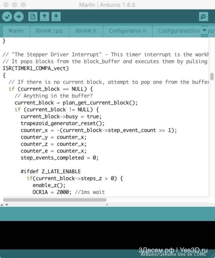
4. Firmware and printer setup - Marlin.
5. Firmware and printer setup - Repetier-Firmware.
1. Enclosure to choose from any sheet material 6 mm thick (plywood, MDF, acrylic, monolithic polycarbonate, etc.).What you need to buy:
I am periodically asked questions about "raspberries", "oranges" and where it is in general and why. And here I begin to understand that before writing "narrow" instructions for setting up, it would be nice to briefly talk about how this kitchen generally works, from bottom to top and from left to right. Better late than never, so your attention is invited to a kind of educational program on arduins, ramps and other scary words.
The fact that we now have the opportunity to buy or build our own FDM 3D printer for a reasonable price is due to the RepRap movement. I will not talk about its history and ideology now - what is important for us now is that it was within the framework of RepRap that a certain "gentleman's set" of hardware and software was formed.
In order not to repeat myself, I will say once: within the framework of this material, I consider only "ordinary" FDM 3D printers, not paying attention to industrial proprietary monsters, this is a completely separate universe with its own laws. Household devices with "own" hardware and software will also remain outside the scope of this article. Further, by "3D printer" I mean a fully or partially open device, the "ears" of which stick out of the RepRap.
Let's talk about Atmel's eight-bit microcontrollers with AVR architecture, in relation to 3D printing. Historically, the "brain" of most printers is an eight-bit microcontroller from Atmel with AVR architecture, in particular, ATmega 2560. And another monumental project ^ its name - Arduino is to blame for this. Its software component is of no interest in this case - the Arduino code is easier for beginners to understand (compared to conventional C / C ++), but it works slowly, and eats resources as free.
Therefore, when arduinists run into a lack of performance, they either give up the idea, or slowly turn into embedders ("classic" microcontroller device developers). At the same time, by the way, it is absolutely not necessary to leave the Arduino hardware - it (in the form of Chinese clones) is cheap and convenient, it simply begins to be considered not as an Arduino, but as a microcontroller with the minimum necessary piping.

In fact, the Arduino IDE is used as an easy-to-install set of compiler and programmer, the Arduino "language" in the firmware and does not smell.
But I digress a little. The task of the microcontroller is to issue control actions (perform the so-called "kick") in accordance with the instructions received and the readings of the sensors. A very important point: these low-power microcontrollers have all the typical features of a computer - a small chip has a processor, RAM, read-only memory (FLASH and EEPROM). But if the PC is running an operating system (and it already "resolves" the interaction of hardware and numerous programs), then on the "mega" we have exactly one program that works directly with the hardware. It is fundamentally.
You can often hear the question why they don’t make 3D printer controllers based on a microcomputer like the same Raspberry Pi. It would seem that the computing power is a wagon, you can immediately make a web interface and a bunch of convenient goodies ... But! This is where we enter the dreaded realm of real-time systems.
Wikipedia gives the following definition: "A system that must respond to events in an environment external to the system or act on the environment within the required time constraints." If it’s completely on the fingers: when the program runs “on the hardware” directly, the programmer fully controls the process and can be sure that the actions laid down will occur in the right sequence, and that on the tenth repetition some other will not wedge between them. And when we are dealing with the operating system, then it decides when to execute the user program, and when to be distracted by working with a network adapter or a screen. Of course, you can influence the operation of the OS. But predictable work with the required accuracy can be obtained not in Windows, and not in Debian Linux (on variations of which micro-PCs mainly work), but in the so-called RTOS (real-time operating system, RTOS), originally developed (or modified) for these tasks. The use of RTOS in RepRap today is a terrible exotic. But if you look at the developers of CNC machines, there is already a normal phenomenon.

For example, the board is not on an AVR, but on a 32-bit NXP LPC1768. It's called Smoothieboard. Relics - a lot, functions - too.
And the thing is that at this stage of RepRap development, "8 bits will be enough for everyone." Yes, 8 bit, 16 MHz, 256 kilobytes of flash memory and 8 kilobytes of RAM. If not all, then a lot. And for those who are not enough (this happens, for example, when working with a 1/32 microstep and with a graphic display, as well as with delta printers, which have relatively complex mathematics for calculating movements), more advanced microcontrollers are offered as a solution. Different architecture, more memory, more computing power. And the software still mostly works "on hardware", although some flirting with RTOS looms on the horizon.
Before we move on to the second part and start talking about RepRap electronics. I want to try to deal with one controversial point - potential problems with 1/32 microstepping. If you theoretically estimate, then based on the technical capabilities of the platform, its performance should not be enough to move at a speed above 125 mm / s.
To test this assumption, I built a "test bench", connected a logic analyzer, and began to experiment. The "stand" is a classic "Mega + RAMPS" sandwich with a converted five-volt power supply, one DRV8825 driver (1/32) is installed. It makes no sense to mention the motor and current - the results are completely identical with a "full" connection, with a driver and no motor, with no driver and no motor.

The analyzer is a Chinese clone of Saleae Logic, connected to the STEP pin of the driver. Marlin 1.0.2 firmware is configured as follows: Max speed 1000mm/s per axle, CoreXY, 160 steps per mm (this is for a 1.8 pitch motor, 20 tooth pulley, GT2 belt and 1/32 crush).
Experimental technique
We set a small acceleration (100 mm/s) and start moving along the X axis by 1000 mm with different target speeds. For example, G code G1 X1000 F20000. 20000 is the speed in mm/min, 333.3(3) mm/s. And we look at what we have with STEP impulses.
General results

That is, starting from an interruption frequency of 10 kHz, we get an effective frequency of up to 40 kHz. Applying a little arithmetic to this, we get this:
up to 62.5 mm/s - one step per interruption;
up to 125 mm/s - two steps per interruption;
up to 250 mm/s - four steps per interruption.
This is theory. What about in practice? And if you set more than 250 mm / s? Well, okay, I give G1 X1000 F20000 (333.3(3) mm/s) and analyze the result. The measured pulse frequency in this case is almost 40 kHz (250 mm/s). Logically.

At speeds above 10000 mm/min (166.6(6) mm/s) I consistently get clock dips. On both engines synchronously (remember, CoreXY). They last 33 ms, they are approximately 0.1 s before the start of the speed decrease. Sometimes there is the same dip at the beginning of the movement - 0.1 after the completion of the speed increase. In general, there is a suspicion that it steadily disappears at speeds up to 125 mm / s - that is, when 4 steps per interrupt are not applied, but this is only a suspicion.
How to interpret this result - I do not know. It does not correlate with any external influences - it does not coincide with communication via the serial port, the firmware is assembled without the support of any displays and SD cards.
Thoughts
1. If you do not try to cheat something with Marlin, the speed ceiling (1.8", 1/32, 20 teeth, GT2) is 250 mm / s.
2. At speeds above 125 mm / s (hypothetically) there is a glitch with a clock failure. Where and how it will manifest itself in real work - I cannot predict.
3. In more difficult conditions (when the processor intensively calculates something), it will definitely not be better, but rather worse. How much is a question for a much more monumental study, because you have to compare the movements planned by the program with the actually issued (and captured) impulses - I don’t have enough gunpowder for this.
In the second part, we will talk about how the microcontroller described earlier controls stepper motors.
Move it!
In "rectangular" printers, you need to provide movement along three axes. Let's say move the print head in X and Z, and the table with the model in Y. This, for example, is the familiar Prusa i3, beloved by Chinese sellers and our customers. Or Mendel. You can only move the head in X, and the table in Y and Z. This is, for example, Felix. I almost immediately fell into 3D printing (with MC5, which has an XY-table and a Z-head), so I became a fan of moving the head in X and Y, and the table in Z. This is the kinematics of Ultimaker, H-Bot, CoreXY.

In short, there are many options. Let's assume for simplicity that we have three motors, each of which is responsible for the movement of something along one of the axes in space, according to the Cartesian coordinate system. In “pryusha”, two engines are responsible for vertical movement, this does not change the essence of the phenomenon. So, three motors. Why is there a quartet in the title? Because you still need to supply plastic.
In leg
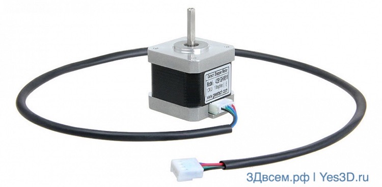
Stepper motors are traditionally used. Their feature is a tricky design of the stator windings, a permanent magnet is used in the rotor (that is, there are no contacts relating to the rotor - nothing is erased and does not spark). A stepper motor, as its name suggests, moves discretely. The most common sample within RepRap has a NEMA17 size (in fact, the seat is regulated - four mounting holes and a protrusion with a shaft, plus two dimensions, the length can vary), is equipped with two windings (4 wires), and its full turn consists of 200 steps (1.8 degrees per step).

In the simplest case, the rotation of a stepper motor is carried out by successively activating the windings. By activation is meant the application of a supply voltage of direct or reverse polarity to the winding. In this case, the control circuit (driver) must not only be able to switch "plus" and "minus", but also limit the current consumed by the windings. The full current switching mode is called full-step, and it has a significant drawback - at low speeds the motor twitches terribly, at slightly higher speeds it starts to rattle. In general, nothing good. To increase the smoothness of movement (the accuracy does not increase, the discreteness of full steps does not disappear anywhere!) A microstepping control mode is used. It lies in the fact that the limitation of the current supplied to the windings varies in a sinusoidal manner. That is, one real step accounts for a certain number of intermediate states - microsteps.
To implement microstep motor control, specialized microcircuits are used. Within RepRap there are two of them - A4988 and DRV8825 (modules based on these microcircuits are usually called the same). Plus, the ingenious TMC2100s are starting to creep in here. Stepper motor drivers are traditionally made in the form of modules with legs, but they are also soldered to the board. The second option is less convenient at first glance (there is no way to change the driver type, and if it fails, sudden hemorrhoids occur), but there are also advantages - advanced boards usually have software control of the motor current, and soldered drivers are soldered on multilayer boards with normal wiring are cooled through the “belly” of the chip onto the heat-removing layer of the board.
But, again, speaking of the most common option - a driver chip on its own printed circuit board with legs. It has three signals at the input - STEP, DIR, ENABLE. Three more pins are responsible for the microstepping configuration. We apply or do not apply a logical unit to them by setting or removing jumpers (jumpers). The microstep logic is hidden inside the chip, we don’t need to get into it. Only one thing can be remembered - ENABLE allows the driver to work, DIR determines the direction of rotation, and the pulse applied to STEP tells the driver that it is necessary to take one microstep (in accordance with the configuration specified by the jumpers).
The main difference between DRV8825 and A4988 is support for 1/32 pitch splitting. There are other subtleties, but this is enough for a start. Yes, modules with these chips are inserted into the control board pads in different ways. Well, it happened in terms of the optimal layout of the module boards. And inexperienced users burn.

In general, the higher the crushing value, the smoother and quieter the motors run. But at the same time, the load on the “foot-kick” increases - after all, you have to issue STEP more often. I personally don’t know about problems when working at 1/16, but when there is a desire to completely switch to 1/32, there may already be a lack of “mega” performance. The TMC2100 stand out here. These are drivers that receive a STEP signal with a frequency as for 1/16, and themselves “think up” up to 1/256. The result is smooth, quiet operation, but not without flaws. First, the modules on the TMC2100 are expensive. Secondly, I personally (on a self-made CoreXY called Kubocore) have problems with these drivers in the form of missing steps (respectively, positioning failure) at accelerations above 2000 - this is not the case with DRV8825.
To summarize in three words: each driver needs two legs of the microcontroller to set the direction and issue a microstep pulse. The driver permission input is usually common to all axes - there is just one engine shutdown button in the Repetier-Host. Microstepping is good in terms of smoothness of movement and the fight against resonances and vibration. The maximum motor current limitation must be adjusted using the trimmer resistors on the driver modules. If the current is exceeded, we will get excessive heating of the drivers and motors, if the current is insufficient, there will be skipping steps.
Spotykach
RepRap does not provide position feedback. That is, the control controller program does not know where the moving parts of the printer are currently located. Strange, of course. But with direct mechanics and normal settings, it works. Before printing, the printer moves everything that is possible to the initial position, and it is already repelled from it in all movements. So, the opposite phenomenon of skipping steps. The controller gives impulses to the driver, the driver tries to turn the rotor. But with excessive load (or insufficient current), a "bounce" occurs - the rotor starts to turn, and then returns to its original position. If this happens on the X or Y axis, we get a layer shift. On the Z axis - the printer starts to "smear" the next layer into the previous one, also nothing good. It is not uncommon for a skip to occur on the extruder (caused by a clogged nozzle, overfeed, insufficient temperature, too little distance to the bed at the start of printing), then we have partially or completely unprinted layers.
With how the skipping of steps manifests itself, everything is relatively clear. Why is this happening? Here are the main reasons:
1. Too much load. For example, a stretched belt. Or skewed guides. Or dead bearings.
2. Inertia. To quickly accelerate or decelerate a heavy object, you need to expend more effort than with a smooth change in speed. Therefore, the combination of high accelerations with a heavy carriage (or table) may well cause skipping steps during a sharp start.
3. Incorrect driver current setting.
The last point is generally a topic for a separate article. In short, each stepper motor has such a parameter as the rated current. It is in the range of 1.2 - 1.8 A for common motors. So, with such a current limit, everything should work well for you. If not, then the engines are overloaded. If there is no skipping steps with a lower limit - generally fine. When the current decreases relative to the nominal value, the heating of the drivers decreases (and they can overheat) and motors (more than 80 degrees is not recommended), plus, the volume of the “song” of the steppers decreases.

In the first part of the cycle, I talked about small weak 8-bit Atmel microcontrollers of the AVR architecture, specifically about the Mega 2560, which "rules" most amateur 3D printers. The second part is devoted to the control of stepper motors. Now - about heating devices.
The essence of FDM (fused deposition modeling, trademark of Stratasys, usually everyone doesn’t care, but cautious people came up with FFF - fused filament fabrication) in the layer-by-layer fusing of the filament. Fusion occurs as follows: the filament must melt in a certain zone of the hot end, and the melt, pushed by the solid part of the rod, is squeezed out through the nozzle. When the print head moves, the filament is simultaneously extruded and smoothed to the previous layer by the end of the nozzle.

It would seem that everything is simple. We cool the upper part of the thermal barrier tube, and heat the lower part, and everything is fine. But there is a nuance. It is necessary to maintain the temperature of the hotend with decent accuracy so that it walks only within small limits. Otherwise, we get an unpleasant effect - some of the layers are printed at a lower temperature (the filament is more viscous), some at a higher temperature (more liquid), and the result looks like a Z-wobble. And now, we have a full-length question of stabilizing the temperature of the heater, which has a very small inertia - due to the low heat capacity, any external “sneeze” (draft, blower fan, you never know what else) or a control error instantly leads to a noticeable temperature change.
Here we invade the halls of the discipline called TAU (automatic control theory). Not exactly my specialty (IT specialist, but graduating from the department of automated control systems), but we had such a course, with a teacher who showed slides on a projector and periodically freaked out over them with comments: “Oh, I trusted these students to translate lectures into electronic form, they are here they stuck such jambs, well, nothing, you will figure it out. Okay, lyrical memories aside, let's welcome the PID controller.
You can't write about PID control without this formula. In the framework of this article, it is just for beauty.
I highly recommend that you read the article, it is written quite clearly about PID control. If we simplify it completely, then the picture looks like this: we have some target temperature value. And with a certain frequency, we get the current temperature value, and we need to issue a control action in order to reduce the error - the difference between the current and target value. The control action in this case is a PWM signal to the gate of the field-effect transistor (mosfet) of the heater. From 0 to 255 "parrots", where 255 is the maximum power. For those who do not know what PWM is - the simplest description of the phenomenon.

So. Each “tact” of working with the heater, we need to make a decision about issuing from 0 to 255. Yes, we can simply turn the heater on or off without bothering with PWM. Let's say the temperature is above 210 degrees - do not turn it on. Below 200 - enable. Only in the case of the hotend heater, such a spread will not suit us, we will have to increase the frequency of the “cycles” of work, and these are additional interruptions, the operation of the ADC is also not free, and we have extremely limited computing resources. In general, it is necessary to manage more accurately. Therefore PID control. P - proportional, I - integral, D - differential. The proportional component is responsible for the "direct" response to the deviation, the integral component - for the accumulated error, the differential component - in response to the processing of the error change rate.
To put it even simpler, the PID controller issues a control action depending on the current deviation, taking into account the "history" and the rate of change of the deviation. Infrequently, I hear about the calibration of the Marlin PID controller, but there is such a function, as a result we get three coefficients (proportional, integral, differential) that allow us to most accurately control our heater, and not spherical in vacuum. Those who wish can read about the M303 code.

Hot end temperature graph (Repetier-Host, Marlin)

To illustrate the extremely low inertia of the hot end, I just blew on it.
Okay, this is about the hotend. Everyone has it when it comes to FDM / FFF. But some like it hot, so there is a great and terrible, burning mosfets and ramps, heating table. From an electronic point of view, everything is more complicated with it than with a hot end - the power is relatively large. But from the standpoint of automatic control, it is easier - the system is more inert, and the permissible deviation amplitude is higher. Therefore, in order to save computing resources, the table is usually controlled according to the bang-bang principle (“puff-puff”), I described this approach above. While the temperature has not reached a maximum, we heat by 100%. Then let it cool down to an acceptable minimum, and warm it up again. I also note that when connecting a hot table through an electromechanical relay (and this is often done to “unload” the mosfet), only bang-bang is a valid option, you do not need to PWM the relay.
Sensors
Finally - about thermistors and thermocouples. The thermistor changes its resistance with temperature, is characterized by a nominal resistance at 25 degrees and a temperature coefficient. In fact, the device is non-linear, and in the same “marlin” there are tables for converting the data received from the thermistor into temperature. The thermocouple is a rare visitor to RepRap, but it comes across. The principle of operation is different, the thermocouple is a source of EMF. Well, that is, it produces a certain voltage, the value of which depends on temperature. It does not connect directly to RAMPS and similar boards, but active adapters exist. Interestingly, tables for metal (platinum) resistance thermometers are also provided in the "marlin". Not such a rare thing in industrial automation, but whether it is found "live" in RepRap - I do not know.
A 3D printer operating on the FDM / FFF principle consists, in fact, of three parts: mechanics (moving something in space), heating devices and electronics that control it all.

In general terms, I have already told how each of these parts works, and now I will try to speculate on the topic "how it is assembled into one device." Important: I will describe a lot from the standpoint of a homemade handicraftsman who is not equipped with wood or metalworking machines and operates with a hammer, drill and hacksaw. And yet, in order not to spray, basically about the "typical" RepRap - one extruder, print area around 200x200 mm.
Least variable

The original E3D V6 and its very unkind price.
I'll start with heaters, there are not very many popular options here. Today, the hotend E3D is the most common among do-it-yourselfers.
More precisely, his Chinese clones are of very floating quality. I won't talk about suffering with polishing an all-metal barrier or using a Bowden tube "to the nozzle" - this is a separate discipline. From personal little experience - a good metal barrier works great with ABS and PLA, without a single break. A bad metal barrier works fine with ABS and disgustingly (up to "no way" - with PLA), and in this case it is easier to put an equally bad thermal barrier, but with a Teflon insert.
In general, E3Ds are very convenient - you can experiment with both thermal barriers and heaters - both "small" and Volcano are available (for thick nozzles and fast brutal printing). Also conditional division, by the way. Now I use Volcano with a 0.4 nozzle. And some invent a spacer sleeve, and work quietly with short nozzles from a regular E3D.
Minimum program - buy a typical Chinese kit "E3D v6 + heater + set of nozzles + cooler". Well, I immediately recommend a pack of different thermal barriers, so that when it comes to this, you don’t have to wait for the next package.

The second heater is not a second hot end (although it's not bad either, but we won't dive in), but a table. You can rank yourself among the knights of the cold table, and not raise the issue of lower heating at all - yes, then the choice of filament narrows down, you will have to think a little about securely fixing the model on the table, but then you will never know about charred RAMPS terminals, deep relationships with thin wires and Elephant's foot print defect. Okay, let the heater still be. Two popular options are foil fiberglass and aluminum.
The first one is simple, cheap, but curved and "liquid", requires normal fastening to a rigid structure and even glass on top. Second
In fact, the same printed circuit board, only as a substrate - aluminum. Good own stiffness, uniform heating, but more expensive.
An unobvious drawback of an aluminum table is when a Chinese badly attaches thin wires to it. It is easy to replace wires on a textolite table, having basic soldering skills. But soldering 2.5 squares to the tracks of an aluminum board is an advanced level task, given the excellent thermal conductivity of this metal. I used a powerful soldering iron (which has a wooden handle and a finger tip), and I had to call in a hot air soldering station to help him.
The most interesting

3D printer with "robot arm" kinematics.
The most delicious part is the choice of kinematics. In the first paragraph, I vaguely mentioned mechanics as a means of "moving something in space." Now, just to what and where to move. In general, we need to get three degrees of freedom. And you can move the print head and the table with the part, hence all the variety. There are radical designs with a fixed table (delta printers), there are attempts to use the schemes of milling machines (XY-table and Z-head), there are perversions in general (polar printers or SCARA-mechanics borrowed from robotics). You can talk about all this chaos for a long time. So, I will limit myself to two schemes.
"Pryusha"
XZ-portal and Y-table. Politically correct I will call this scheme "well-deserved". Everything is more or less clear, realized a hundred times, finished, modified, put on rails, scaled in dimensions.
The general idea is as follows: there is the letter "P", along the legs of which a crossbar rides, driven by two synchronized engines using a "screw-nut" transmission (a rare modification - with belts). An engine hangs on the crossbar, which drags the carriage left and right by the belt. The third degree of freedom is a table moving back and forth. There are advantages of the design, for example, knowledge up and down or extreme simplicity in handicraft implementation from improvised materials. The disadvantages are also known - the problem of synchronization of Z engines, the dependence of print quality on two pins, which should be more or less the same, it is difficult to accelerate to high speeds (since a relatively heavy inert table is moving).
Z-table
When printing, the Z coordinate changes the slowest, and only in one direction. So we will move the table vertically. Now we need to figure out how to move the print head in one plane. There is a solution to the problem "in the forehead" - in fact. we take the “pryusha” portal, put it on its side, replace the studs with a belt (and remove the extra engine, replacing it with a gear), turn the hotend 90 degrees, voila, we get something like a MakerBot Replicator (not the latest generation).
How else to improve this scheme? It is necessary to achieve a minimum mass of moving parts. If we abandon the direct extruder and feed the filament through the tube, there is still an X engine that needs to be rolled along the guides for nothing. And this is where the real engineering ingenuity comes in. In Dutch, it looks like a bunch of shafts and belts in a box called Ultimaker. The design has been taken to the point where many consider the Ultimaker to be the best desktop 3D printer.
But there are simpler engineering solutions. For example, H-Bot. Two fixed motors, one long belt, a handful of rollers. And this case allows you to move the carriage in the XY plane by rotating the motors in one direction or in different directions. Beautiful. In practice, it imposes increased requirements on the rigidity of the structure, which somewhat complicates the manufacture of matches and acorns, especially when using wooden bearings.

Classic CoreXY with crossed straps.
A more complex scheme, with two belts and a larger bunch of rollers - CoreXY. I consider it the best option for implementation when you have already collected your own or Chinese “pryusha”, but the creative itch has not subsided. Can be made from plywood, aluminum profiles, stools and other unnecessary pieces of furniture. In principle, the result is similar to the H-Bot, but less prone to jamming and twisting the frame into a ram's horn.
Electronics
If you need to save money, then Mega + RAMPS in the Chinese version is simply out of competition. If there is no special knowledge in electrical and electronics, and nerves are not superfluous, then it is better to look towards more expensive, but well-made boards from Makerbase or Geeetech.
The main sores of the sandwich in the form of "wrong" output transistors and the power supply of the entire five-volt collective farm through the stabilizer on the Arduino board were cured there. If we talk about completely alternative options, then I'm waiting for the opportunity to purchase an LPC1768 board, for example, the same MKS SBase, and have fun with 32-bit ARM and Smoothieware firmware. And in parallel, I am slowly studying the Teacup firmware in relation to the Arduino Nano and Nanoheart.
Do-it-yourselfer
Well, let's say you decide to blind your bike. I don't see anything wrong with that.
In general, it is necessary to start from financial possibilities and from what can be found in a garage or basement. And also from the presence or absence of access to machines and the radius of curvature of the hands. Roughly speaking, there is an opportunity to spend 5 thousand rubles - well, we manage with the bare minimum. For a dozen, you can already roam a little, and approaching the budget to 20 thousand pretty much unties your hands. Of course, the opportunity to buy a Chinese pryusha constructor makes life much easier - you can both understand the basics of 3D printing and get an excellent tool for developing a self-propelled gun.
Moreover, most of the details (engines, electronics, part of the mechanics) will easily migrate to the next design. In short, we buy acrylic junk, finish sawing to a sane state, print parts for the next printer, use the previous one for spare parts, lather, rinse, repeat.
 Start building Kubocore 2.
That's probably all. Perhaps it turned out a little gallop. But it is difficult to grasp the immensity within the framework of a general review material in a different way. Although, I threw in useful links for reflection, the seeker will find it in any way. Questions and additions are traditionally welcome. Well, yes, in the foreseeable future there will be a continuation - already about specific decisions and rakes in the framework of the design and construction of Kubocore 2.
Additive printers are expensive today. Many people have to spend hundreds or even thousands of dollars just to get this high-tech machine. The method of self-assembly of devices for three-dimensional printing is of interest to many. Why not try to print exactly the same device on the printer, if the shape of the parts created can be any? Modern engineers really have the opportunity to assemble a 3D printer with their own hands.
Modern designers are confident that 3D printing devices should be available to everyone. In 2004, mechanisms capable of reproducing themselves were discussed for the first time. It was planned to create installations that print copies of their own components.
The pioneer in this area managed to recreate more than half of these details. The second generation of devices used metal alloys, marble dust, talc and plastic to create prints. Such installations could not be called ideal inventions. They needed improvement.
The base price of a conventional component development platform is 350 euros. Equipment that provides the ability to print electrical circuits costs ten times more. In order to copy such settings, you will have to make an effort.

For self-assembly, the standard EWaste model is suitable. Costs less than $60. If you can find suitable components that can be removed from unnecessary electrical appliances, it is quite possible to assemble it. To do this, you will need a NEMA 17 motor, a PC power supply, a DVD drive, heat shrink tubing and connectors.
Another design can be assembled from components of disassembled laser printers in combination with steel rails, metal profiles and plastic bearings. 4 motors are attached to the frame, two of them must support the microstep function. You will also need to use several connecting wires, optical sensors and a thermostat for the cell. Many users note that they managed to design a 3D printer with their own hands. You can see the drawings in the article, they are available for review. Conventional home-made machines do not have outstanding properties, but they cope with printing small plastic products.
There is always an opportunity to collect something special. The scheme of an inexpensive device for three-dimensional printing was proposed by Chinese experts. The open component market makes it possible to purchase all the necessary components of such a mechanism. Chinese designers used the Makeblock frame, which anyone can purchase in the company's store.
Now there is nothing difficult in creating a 3D printer with your own hands. The device is equipped with an Arduino MEGA 2560 electrical board. The control can be carried out by an ordinary user of a personal computer by installing the necessary software in advance.

Everyone will have to choose the assembly technology. All generations of modern self-reproducing devices are characterized by rapid development. A factory-assembled printer is much more expensive than printed components.
Astronauts plan to take several of these printers with them into space in the near future. The payload and useful area of the aircraft can be saved thanks to these wonderful devices. Astronauts will have to assemble a 3D printer with their own hands. From a printer used, for example, on the moon, very good construction equipment for the construction of space bases can turn out. Fine sand will be used as ink.
It will not be difficult for modern engineers to make a 3D printer with their own hands. Reprap designs make it possible to save the wallet from unnecessary costs. Finished samples require customization. This may adversely affect print quality. It should be mentioned that self-assembly will require a lot of patience and considerable knowledge of engineering.
Not everyone has the opportunity to buy a 3D printer, but many dream of this device. In order not to throw away money, you can look for suitable components in other electronic devices and use them as the basis of a home-made printing device. The total cost of such a printer will not exceed $100. It's cheap, given that the device is homemade. Do-it-yourself 3D printers can be created by all amateurs who are familiar with the basics of engineering thanks to the described principles.

You should start with an analysis of the specifics of the operation of universal CNC systems. It is necessary to learn the list of basic commands for controlling the device using the program code. A plastic motor power regulator and an extruder are attached to the structure. The composition of each device, developed independently, will include several basic components: a case, a power supply, a stepper motor, a controller, a print head and rails.
As parts used at this stage, you can use ordinary CD / DVD drives left over from old computers. You will need a floppy drive. At this stage, you should make sure that the drive motors are not running on DC, but in steps. Of all the existing motors needed to mount a DIY 3D printer, the Nema 23 is the best option when used in a plastic extruder.
Additional electronics will also be required, the choice of which will depend on financial capabilities and its availability on sale. It is necessary to prepare all cables, power supply, heat-resistant tubes and connectors. The wires are soldered to the stepper motors.

The drives that feed the plastic fibers will be assembled from a MK7 / MK8 gear and a Nema 23 stepper motor. You also need to download software to control the elements of the extruder of the printing machine. Also don't forget the drivers.
The plastic material will be drawn into the extruder and enter the heating chamber. The heated ink then passes through heat-resistant tubes. To assemble a direct drive, you need to connect the frame mount to the stepper motor. The data obtained on the extruder are exposed in the Repetier program. Any engineer can make such a 3D printer with their own hands.

Preparation of the device for the first test can be considered completed. The diameter of the plastic fiber in the extruder should be 1.75 mm. This thickness will not require a lot of energy during printing. It is recommended to fill the printer with PLA plastic due to its fusibility, safety and ease of use.
Repetier is activated and Skeinforge profile slices are launched. To check the calibration, you can print some simple figure. If the assembly was not done correctly, configuration problems can be detected almost immediately by checking the dimensions of the received product.
To get started, you need to open the STL model, determine the shape to print, enter the appropriate g-code. The extruder heats up and then begins to melt the plastic. It is necessary to squeeze out some material to check the operation of the device. The above instructions describe the basic principles of work that must be followed in order to make a 3D printer with your own hands.
Today, every engineer understands that it is quite possible to create a device for 3D printing on their own. At the stage of collecting information, no difficulties will arise. We have described the whole procedure in detail above.

For the successful implementation of the task, it is necessary to understand the manufacturing technology of the device and determine the main problems that have to be dealt with. You need to get a drawing (see above), pick up all the components, do a lot of work and learn a considerable amount of additional information. The results are sure to please.
Such a device can create small figures, and there will be little practical use from it, but for his own pleasure, every engineer with a sufficient level of information support is able to assemble such a device. Some may find the process interesting, not the products themselves. If an engineer wants to make a 3D printer with his own hands for the manufacture of large parts, in any case, he will have to fork out, because the components for such devices are much more expensive. Those who do not have problems with funds will have to torment themselves with the search for the device necessary for self-assembly of a large printer. Good luck!
I am periodically asked questions about "raspberries", "oranges" and where it is in general and why. And here I begin to understand that before writing “narrow” setup instructions, it would be nice to briefly talk about how this kitchen generally works, from bottom to top and from left to right. Better late than never, so your attention is invited to a kind of educational program on arduins, ramps and other scary words.
The fact that we now have the opportunity to buy or build our own FDM 3D printer for a reasonable price is due to the RepRap movement. I won’t talk about its history and ideology now - it’s important for us now that it was within the framework of RepRap that a certain “gentleman’s set” of hardware and software was formed.
In order not to repeat myself, I will say once: within the framework of this material, I consider only “ordinary” FDM 3D printers, not paying attention to industrial proprietary monsters, this is a completely separate universe with its own laws. Household devices with "own" hardware and software will also remain outside the scope of this article. Further, by "3D printer" I mean a fully or partially open device, the "ears" of which stick out of the RepRap.
Let's talk about Atmel's eight-bit microcontrollers with AVR architecture, in relation to 3D printing. Historically, the "brain" of most printers is an eight-bit Atmel microcontroller with the AVR architecture, in particular, the ATmega 2560. And another monumental project ^ its name is Arduino is to blame. Its software component is of no interest in this case - the Arduino code is easier to understand for beginners (compared to conventional C / C ++), but it works slowly, and eats resources as free.
Therefore, when arduinists run into a lack of performance, they either give up the idea or slowly turn into embedders (“classic” microcontroller device developers). At the same time, by the way, it is absolutely not necessary to abandon the Arduino hardware - it (in the form of Chinese clones) is cheap and convenient, it simply begins to be considered not as an Arduino, but as a microcontroller with the minimum necessary strapping.
In fact, the Arduino IDE is used as an easy-to-install set of a compiler and a programmer, the Arduino “language” in the firmware and does not smell.
But I digress a little. The task of the microcontroller is to issue control actions (to carry out the so-called “foot kick”) in accordance with the instructions received and the readings of the sensors. A very important point: these low-power microcontrollers have all the typical features of a computer - a small chip has a processor, RAM, read-only memory (FLASH and EEPROM). But if the PC is running an operating system (and it already “resolves” the interaction of hardware and numerous programs), then on the “mega” we have exactly one program that works directly with the hardware. It is fundamentally.
You can often hear the question why they don’t make 3D printer controllers based on a microcomputer like the same Raspberry Pi. It would seem that the computing power is a wagon, you can immediately make a web interface and a bunch of convenient goodies ... But! This is where we enter the dreaded realm of real-time systems.
Wikipedia gives the following definition: "A system that must respond to events in an environment external to the system or act on the environment within the required time constraints." If it’s completely on your fingers: when the program runs “on the hardware” directly, the programmer completely controls the process and can be sure that the actions laid down will occur in the right sequence, and that on the tenth repetition some other will not wedge between them. And when we are dealing with the operating system, then it decides when to execute the user program, and when to be distracted by working with a network adapter or a screen. Of course, you can influence the operation of the OS. But predictable work with the required accuracy can be obtained not in Windows, and not in Debian Linux (on variations of which micro-PCs mainly work), but in the so-called RTOS (real-time operating system, RTOS), originally developed (or modified) for these tasks. The use of RTOS in RepRap today is a terrible exotic. But if you look at the developers of CNC machines, there is already a normal phenomenon.
For example, the board is not on an AVR, but on a 32-bit NXP LPC1768. It's called Smoothieboard. Power - a lot, functions - too.
And the thing is that at this stage of development of RepRap, "8 bits will be enough for everyone." Yes, 8 bit, 16 MHz, 256 kilobytes of flash memory and 8 kilobytes of RAM. If not all, then a lot. And for those who are not enough (this happens, for example, when working with a 1/32 microstep and with a graphic display, as well as with delta printers, which have relatively complex mathematics for calculating movements), more advanced microcontrollers are offered as a solution. Different architecture, more memory, more computing power. And the software still mostly works "on hardware", although some flirting with RTOS looms on the horizon.
Before we move on to the second part and start talking about RepRap electronics. I want to try to deal with one controversial point - potential problems with 1/32 microstepping. If you theoretically estimate, then based on the technical capabilities of the platform, its performance should not be enough to move at a speed above 125 mm / s.
To test this assumption, I built a "test bench", connected a logic analyzer, and began to experiment. The “stand” is a classic Mega + RAMPS sandwich with a converted five-volt power supply, one DRV8825 driver (1/32) is installed. It makes no sense to mention the motor and current - the results are completely identical with a “full” connection, with a driver and no motor, and no driver and motor.
That is, starting from an interruption frequency of 10 kHz, we get an effective frequency of up to 40 kHz. Applying a little arithmetic to this, we get this:
up to 62.5 mm / s - one step per interrupt;
up to 125 mm / s - two steps for interruption;
up to 250 mm/s - four steps per interruption.
This is theory. What about in practice? And if you set more than 250 mm / s? Well, okay, I give G1 X1000 F20000 (333.3(3) mm/s) and analyze the result. The measured pulse frequency in this case is almost 40 kHz (250 mm/s). Logically.
At speeds above 10000 mm/min (166.6(6) mm/s) I consistently get clock dips. On both engines synchronously (remember, CoreXY). They last 33 ms, they are approximately 0.1 s before the start of the speed decrease. Sometimes there is the same dip at the beginning of the movement - 0.1 after the completion of the speed increase. In general, there is a suspicion that it steadily disappears at speeds up to 125 mm / s - that is, when 4 steps per interrupt are not applied, but this is only a suspicion.
I don't know how to interpret this result. It does not correlate with any external influences - it does not coincide with communication over a serial port, the firmware is assembled without support for any displays and SD cards.
Thoughts
1. If you don’t try to cheat with Marlin, the speed ceiling (1.8″, 1/32, 20 teeth, GT2) is 250 mm/s.
2. At speeds above 125 mm / s (hypothetically) there is a glitch with a clock failure. Where and how it will manifest itself in real work - I cannot predict.
3. In more difficult conditions (when the processor intensively calculates something), it will definitely not be better, but rather worse. How much is a question for a much more monumental study, because it will be necessary to compare the movements planned by the program with the actually issued (and captured) impulses - I don’t have enough gunpowder for this.
In the second part, we will talk about how the microcontroller described earlier controls stepper motors.
Move it!
In "rectangular" printers, you need to provide movement along three axes. Let's say move the print head in X and Z, and the table with the model in Y. This is, for example, the familiar Prusa i3, beloved by Chinese sellers and our customers. Or Mendel. You can only move your head in X, and the table in Y and Z. This is, for example, Felix. I almost immediately got into 3D printing (with the MC5, which has an XY table and a Z head), so I became a fan of moving the head in X and Y, and the table in Z. This is the kinematics of Ultimaker, H-Bot, CoreXY.
In short, there are many options. Let's assume for simplicity that we have three motors, each of which is responsible for the movement of something along one of the axes in space, according to the Cartesian coordinate system. In “pryusha”, two engines are responsible for vertical movement, this does not change the essence of the phenomenon. So, three motors. Why is there a quartet in the title? Because you still need to supply plastic.
In leg
Stepper motors are traditionally used. Their feature is a tricky design of the stator windings, a permanent magnet is used in the rotor (that is, there are no contacts relating to the rotor - nothing is erased and does not spark). A stepper motor, as its name suggests, moves discretely. The most common sample within RepRap has a NEMA17 size (in fact, the seat is regulated - four mounting holes and a protrusion with a shaft, plus two dimensions, the length can vary), is equipped with two windings (4 wires), and its full turn consists of 200 steps (1.8 degrees per step).
In the simplest case, the rotation of a stepper motor is carried out by successively activating the windings. By activation is meant the application of a supply voltage of direct or reverse polarity to the winding. In this case, the control circuit (driver) must not only be able to switch "plus" and "minus", but also limit the current consumed by the windings. The full current switching mode is called full-step, and it has a significant drawback - at low speeds the motor twitches terribly, at slightly higher speeds it starts to rattle. In general, nothing good. To increase the smoothness of movement (the accuracy does not increase, the discreteness of full steps does not disappear anywhere!) A microstepping control mode is used. It lies in the fact that the limitation of the current supplied to the windings varies in a sinusoidal manner. That is, for one real step there are a certain number of intermediate states - microsteps.
To implement microstep motor control, specialized microcircuits are used. Within RepRap, there are two of them - A4988 and DRV8825 (modules based on these microcircuits are usually called the same). Plus, the ingenious TMC2100s are starting to creep in here. Stepper motor drivers are traditionally made in the form of modules with legs, but they are also soldered to the board. The second option is less convenient at first glance (there is no way to change the driver type, and if it fails, sudden hemorrhoids occur), but there are also advantages - on advanced boards, software control of the motor current is usually implemented, and on multilayer boards with normal wiring, soldered drivers are cooled through the “belly” of the chip onto the heat-removing layer of the board.
But, again, speaking of the most common option - a driver chip on its own printed circuit board with legs. It has three signals at the input - STEP, DIR, ENABLE. Three more pins are responsible for the microstepping configuration. We apply or do not apply a logical unit to them by setting or removing jumpers (jumpers). The microstep logic is hidden inside the chip, we don’t need to get into it. Only one thing can be remembered - ENABLE allows the driver to work, DIR determines the direction of rotation, and the pulse applied to STEP tells the driver that it is necessary to take one microstep (in accordance with the configuration specified by the jumpers).
The main difference between DRV8825 and A4988 is the support for 1/32 pitch crushing. There are other subtleties, but this is enough for a start. Yes, modules with these chips are inserted into the control board pads in different ways. Well, it happened in terms of the optimal layout of the module boards. And inexperienced users burn.
In general, the higher the crushing value, the smoother and quieter the motors run. But at the same time, the load on the “foot jumpers” increases - after all, you have to issue STEP more often. I personally don’t know about problems when working at 1/16, but when there is a desire to completely switch to 1/32, there may already be a lack of “mega” performance. The TMC2100 stand out here. These are drivers that receive a STEP signal with a frequency as for 1/16, and themselves “think up” up to 1/256. The result is smooth, quiet operation, but not without flaws. First, the modules on the TMC2100 are expensive. Secondly, I personally (on a self-made CoreXY called Kubocore) have problems with these drivers in the form of skipping steps (respectively, positioning failure) at accelerations above 2000 - this is not the case with DRV8825.
To summarize in three words: each driver needs two legs of the microcontroller to set the direction and issue a microstep pulse. The driver permission input is usually common to all axes - the engine shutdown button in the Repetier-Host is just one. Microstepping is good in terms of smoothness of movement and the fight against resonances and vibration. The maximum motor current limitation must be adjusted using the trimmer resistors on the driver modules. If the current is exceeded, we will get excessive heating of the drivers and motors, if the current is insufficient, there will be skipping steps.
Spotykach
RepRap does not provide position feedback. That is, the control controller program does not know where the moving parts of the printer are currently located. Strange, of course. But with direct mechanics and normal settings, it works. Before printing, the printer moves everything that is possible to the initial position, and it is already repelled from it in all movements. So, the opposite phenomenon of skipping steps. The controller gives impulses to the driver, the driver tries to turn the rotor. But with excessive load (or insufficient current), a “bounce” occurs - the rotor begins to turn, and then returns to its original position. If this happens on the X or Y axis, we get a layer shift. On the Z axis - the printer starts to "smear" the next layer into the previous one, also nothing good. It is not uncommon for a skip to occur on the extruder (caused by a clogged nozzle, overfeed, insufficient temperature, too little distance to the bed at the start of printing), then we have partially or completely unprinted layers.
With how the skipping of steps manifests itself, everything is relatively clear. Why is this happening? Here are the main reasons:
1. Too much load. For example, a stretched belt. Or skewed guides. Or "killed" bearings.
2. Inertia. To quickly accelerate or decelerate a heavy object, you need to expend more effort than with a smooth change in speed. Therefore, the combination of high accelerations with a heavy carriage (or table) may well cause skipping steps during a sharp start.
3. Incorrect driver current setting.
The last point is generally a topic for a separate article. In short, each stepper motor has such a parameter as the rated current. It is in the range of 1.2 - 1.8 A for common motors. So, with such a current limit, everything should work well for you. If not, then the engines are overloaded. If there is no skipping steps with a lower limit, it’s generally fine. When the current decreases relative to the nominal value, the heating of the drivers decreases (and they can overheat) and motors (more than 80 degrees is not recommended), plus, the volume of the “song” of the steppers decreases.
In the first part of the cycle, I talked about small weak 8-bit Atmel microcontrollers of the AVR architecture, specifically about the Mega 2560, which “rules” most amateur 3D printers. The second part is devoted to the control of stepper motors. Now - about heating devices.
The essence of FDM (fused deposition modeling, trademark of Stratasys, usually everyone doesn’t care, but cautious people came up with FFF - fused filament fabrication) in the layer-by-layer fusing of the filament. Fusion occurs as follows: the filament must melt in a certain zone of the hot end, and the melt, pushed by the solid part of the rod, is squeezed out through the nozzle. When the print head moves, the filament is simultaneously extruded and smoothed to the previous layer by the end of the nozzle.
It would seem that everything is simple. We cool the upper part of the thermal barrier tube, and heat the lower part, and everything is fine. But there is a nuance. It is necessary to maintain the temperature of the hotend with decent accuracy so that it walks only within small limits. Otherwise, we get an unpleasant effect - some of the layers are printed at a lower temperature (the filament is more viscous), some at a higher temperature (more fluid), and the result looks like a Z-wobble. And now, we have a full-length question of stabilizing the temperature of the heater, which has a very small inertia - due to the low heat capacity, any external "sneeze" (draft, blower fan, you never know what else) or a control error instantly leads to a noticeable temperature change.
Here we invade the halls of the discipline called TAU (automatic control theory). Not exactly my specialty (IT specialist, but graduating from the department of automated control systems), but we had such a course, with a teacher who showed slides on a projector and periodically freaked out over them with comments: “Oh, I trusted these students to translate lectures into electronic form, they are here they stuck such jambs, well, nothing, you will figure it out. Okay, lyrical memories aside, let's welcome the PID controller.
I highly recommend that you read the article, it is written quite clearly about PID control. If we simplify it completely, then the picture looks like this: we have some target temperature value. And with a certain frequency, we get the current temperature value, and we need to issue a control action in order to reduce the error - the difference between the current and target values. The control action in this case is a PWM signal to the gate of the field-effect transistor (mosfet) of the heater. From 0 to 255 "parrots", where 255 is the maximum power. For those who do not know what PWM is - the simplest description of the phenomenon.
So. Each “tact” of working with the heater, we need to make a decision about issuing from 0 to 255. Yes, we can simply turn the heater on or off without bothering with PWM. Let's say the temperature is above 210 degrees - do not turn it on. Below 200 - enable. Only in the case of the hotend heater, such a spread will not suit us, we will have to increase the frequency of the “cycles” of work, and these are additional interruptions, the operation of the ADC is also not free, and we have extremely limited computing resources. In general, it is necessary to manage more accurately. Therefore PID control. P - proportional, I - integral, D - differential. The proportional component is responsible for the “direct” response to the deviation, the integral component is responsible for the accumulated error, the differential component is responsible for processing the rate of error change.
To put it even simpler, the PID controller issues a control action depending on the current deviation, taking into account the "history" and the rate of change of the deviation. Infrequently, I hear about the calibration of the Marlin PID controller, but there is such a function, as a result we get three coefficients (proportional, integral, differential) that allow us to most accurately control our heater, and not spherical in vacuum. Those who wish can read about the M303 code.
To illustrate the extremely low inertia of the hot end, I just blew on it.
Okay, this is about the hotend. Everyone has it when it comes to FDM / FFF. But some like it hot, so there is a great and terrible, burning mosfets and ramps, heating table. From an electronic point of view, everything is more complicated with it than with a hot end - the power is relatively large. But from the standpoint of automatic control, it is easier - the system is more inert, and the permissible deviation amplitude is higher. Therefore, in order to save computing resources, the table is usually controlled according to the bang-bang principle (“puff-puff”), I described this approach above. While the temperature has not reached a maximum, we heat by 100%. Then let it cool down to an acceptable minimum, and warm it up again. I also note that when connecting a hot table through an electromechanical relay (and this is often done to “unload” the mosfet), only bang-bang is a valid option, you do not need to PWM the relay.
Sensors
Finally - about thermistors and thermocouples. The thermistor changes its resistance with temperature, is characterized by a nominal resistance at 25 degrees and a temperature coefficient. In fact, the device is non-linear, and in the same “marlin” there are tables for converting the data received from the thermistor into temperature. The thermocouple is a rare visitor to RepRap, but it comes across. The principle of operation is different, the thermocouple is a source of EMF. Well, that is, it produces a certain voltage, the value of which depends on temperature. It does not connect directly to RAMPS and similar boards, but active adapters exist. Interestingly, tables for metal (platinum) resistance thermometers are also provided in the "marlin". Not such a rare thing in industrial automation, but I don’t know if it is found “live” in RepRap.
A 3D printer operating on the FDM / FFF principle consists, in fact, of three parts: mechanics (moving something in space), heating devices and electronics that control it all.
In general terms, I have already told how each of these parts works, and now I will try to speculate on the topic "how it is assembled into one device." Important: I will describe a lot from the standpoint of a homemade handicraftsman who is not equipped with wood or metalworking machines and operates with a hammer, drill and hacksaw. And yet, in order not to be sprayed, mainly about the "typical" RepRap - one extruder, the print area is around 200x200 mm.
Least variable
The original E3D V6 and its very unkind price.
I'll start with heaters, there are not very many popular options here. Today, the hotend E3D is the most common among do-it-yourselfers.
More precisely, his Chinese clones are of very floating quality. I won’t talk about torment with polishing an all-metal barrier or using a bowden tube “to the nozzle” - this is a separate discipline. From personal little experience - a good metal barrier works great with ABS and PLA, without a single break. A bad metal barrier works fine with ABS and disgustingly (up to “no way” with PLA), and in this case it can be easier to put an equally bad thermal barrier, but with a Teflon insert.
In general, E3Ds are very convenient - you can experiment with both thermal barriers and heaters - both "small" and Volcano are available (for thick nozzles and fast brutal printing). Also conditional division, by the way. Now I use Volcano with a 0.4 nozzle. And some invent a spacer sleeve, and work quietly with short nozzles from a regular E3D.
Minimum program - we buy a typical Chinese kit "E3D v6 + heater + nozzle set + cooler". Well, I immediately recommend a pack of different thermal barriers, so that when it comes to this, you don’t have to wait for the next package.
The second heater is not a second hot end (although it’s also good, but we won’t dive), but a table. You can rank yourself among the knights of the cold table, and not raise the issue of lower heating at all - yes, then the choice of filament narrows, you will have to think a little about securely fixing the model on the table, but then you will never know about charred RAMPS terminals, deep relationships with thin wires and Elephant's foot print defect. Okay, let the heater still be. Two popular options are foil fiberglass and aluminum.
The first one is simple, cheap, but curved and “liquid”, requires normal fastening to a rigid structure and even glass on top. Second
- in fact, the same printed circuit board, only as a substrate - aluminum. Good own stiffness, uniform heating, but more expensive.
An unobvious drawback of an aluminum table is when a Chinese badly attaches thin wires to it. It is easy to replace wires on a textolite table, having basic soldering skills. But soldering 2.5 squares to the tracks of an aluminum board is an advanced task, given the excellent thermal conductivity of this metal. I used a powerful soldering iron (which has a wooden handle and a finger tip), and I had to call in a hot air soldering station to help him.
The most interesting
The most delicious part is the choice of kinematics. In the first paragraph, I vaguely mentioned mechanics as a means of "moving something in space." Now, just to what and where to move. In general, we need to get three degrees of freedom. And you can move the print head and the table with the part, hence all the variety. There are radical designs with a fixed table (delta printers), there are attempts to use the schemes of milling machines (XY-table and Z-head), there are perversions in general (polar printers or SCARA-mechanics borrowed from robotics). You can talk about all this chaos for a long time. So, I will limit myself to two schemes.
"Pryusha"
XZ-portal and Y-table. Politically correct I will call this scheme "well-deserved". Everything is more or less clear, realized a hundred times, finished, modified, put on rails, scaled in dimensions.
The general idea is this: there is the letter “P”, along the legs of which a crossbar rides, driven by two synchronized engines using a “screw-nut” transmission (a rare modification with belts). An engine hangs on the crossbar, which drags the carriage left and right by the belt. The third degree of freedom is a table moving back and forth. There are advantages of the design, for example, knowledge up and down or extreme simplicity in handicraft implementation from improvised materials. The disadvantages are also known - the problem of synchronization of Z engines, the dependence of print quality on two studs, which should be more or less the same, it is difficult to accelerate to high speeds (since a relatively heavy inert table is moving).
Z-table
When printing, the Z coordinate changes the slowest, and only in one direction. So we will move the table vertically. Now we need to figure out how to move the print head in one plane. There is a solution to the problem "in the forehead" - in fact. we take the “pryusha” portal, put it on its side, replace the studs with a belt (and remove the extra engine, replacing it with a gear), turn the hot end 90 degrees, voila, we get something like a MakerBot Replicator (not the latest generation).
How else to improve this scheme? It is necessary to achieve a minimum mass of moving parts. If we abandon the direct extruder and feed the filament through the tube, there is still an X engine that needs to be rolled along the guides for nothing. And this is where the real engineering ingenuity comes in. In Dutch, it looks like a bunch of shafts and belts in a box called Ultimaker. The design has been taken to the point where many consider the Ultimaker to be the best desktop 3D printer.
But there are simpler engineering solutions. For example, H-Bot. Two fixed motors, one long belt, a handful of rollers. And this case allows you to move the carriage in the XY plane by rotating the motors in one direction or in different directions. Beautiful. In practice, it imposes increased requirements on the rigidity of the structure, which somewhat complicates the manufacture of matches and acorns, especially when using wooden bearings.
A more complex scheme, with two belts and a larger bunch of rollers - CoreXY. I consider it the best option for implementation when you have already collected your own or Chinese “pryusha”, but the creative itch has not subsided. Can be made from plywood, aluminum profiles, stools and other unnecessary pieces of furniture. In principle, the result is similar to the H-Bot, but less prone to jamming and twisting the frame into a ram's horn.
Electronics
If you need to save money, then Mega + RAMPS in the Chinese version is simply out of competition. If there is no special knowledge in electrical and electronics, and nerves are not superfluous, then it is better to look towards more expensive, but well-made boards from Makerbase or Geeetech.
The main sores of the sandwich in the form of “wrong” output transistors and the power supply of the entire five-volt collective farm through the stabilizer on the Arduino board were cured there. If we talk about completely alternative options, then I'm waiting for the opportunity to purchase an LPC1768 board, for example, the same MKS SBase, and have fun with 32-bit ARM and Smoothieware firmware. And in parallel, I am slowly studying the Teacup firmware in relation to the Arduino Nano and Nanoheart.
Do-it-yourselfer
Well, let's say you decide to blind your bike. I don't see anything wrong with that.
In general, it is necessary to start from financial possibilities and from what can be found in a garage or basement. And also from the presence or absence of access to machines and the radius of curvature of the hands. Roughly speaking, there is an opportunity to spend 5 thousand rubles - well, we manage with the bare minimum. For a dozen, you can already roam a little, and approaching the budget to 20 thousand pretty much unties your hands. Of course, the opportunity to buy a Chinese pryusha constructor makes life much easier - you can both understand the basics of 3D printing and get an excellent tool for developing a self-propelled gun.
Moreover, most of the details (engines, electronics, part of the mechanics) will easily migrate to the next design. In short, we buy acrylic junk, finish sawing to a sane state, print parts for the next printer, use the previous one for spare parts, lather, rinse, repeat.
That's probably all. Perhaps it turned out a little gallop. But it is difficult to grasp the immensity within the framework of a general review material in a different way. Although, I threw in useful links for reflection, the seeker will find it in any way. Questions and additions are traditionally welcome. Well, yes, in the foreseeable future there will be a continuation - already about specific decisions and rakes in the framework of the design and construction of Kubocore 2.


 with your own hands how to make?")


")
