For a gasoline internal combustion engine, the ignition system is one of the determining ones, although it is difficult to single out any main unit in a car. You can’t go without a motor, but it’s also impossible without a wheel.
The ignition coil creates a high voltage, without which it is impossible to spark and ignite the fuel-air mixture in the cylinders of a gasoline engine.
To understand why there is a reel in a car (this is a popular name), and what part it takes in ensuring movement, one must at least generally understand the design of ignition systems.
A simplified diagram of the bobbin operation is shown below. 
The positive terminal of the coil is connected to the positive terminal of the battery, and the other terminal is connected to the voltage distributor. This connection scheme is classic and is widely used on cars of the VAZ family. To complete the picture, a number of clarifications need to be made:
Mechanical devices were used in old cars: on the VAZ 2106 and the like, but now they are almost completely replaced by electronic ones.
The modern bobbin is a simplified version of the Ruhmkorff induction coil. It was named after the inventor of German origin - Heinrich Ruhmkorff, who was the first to patent in 1851 a device that converts a constant low voltage into an alternating high voltage.
To understand the principle of operation, you need to know the structure of the ignition coil and the basics of radio electronics. 
This is a traditional, common VAZ ignition coil, used for a long time on many other cars. In fact, this is a pulse high-voltage transformer. A secondary winding is wound on a core designed to amplify the magnetic field with a thin wire; it can contain up to thirty thousand turns of wire.
Above the secondary winding is the primary of a thicker wire and with fewer turns (100-300).
The windings are interconnected at one end, the second end of the primary is connected to the batteries, the secondary winding is connected to the voltage distributor with its free end. The common winding point of the coil is connected to a voltage switch. The whole structure is covered by a protective case.
A direct current flows through the "primary" in the initial state. When a spark needs to be generated, the circuit is broken by a switch or distributor. This leads to the formation of high voltage in the secondary winding. Voltage is supplied to the spark plug of the desired cylinder, where a spark is formed, causing the combustion of the fuel mixture. High-voltage wires were used to connect the spark plugs to the distributor.
The single terminal design is not the only one possible, there are other options. 

The main parameter by which the performance of the bobbin is determined is the resistance of the windings. There are average indicators that indicate its serviceability. Although deviations from the norm are not always an indicator of a malfunction.
Using a multimeter, you can check the ignition coil by 3 parameters:
Please note that only the individual ignition coil can be tested in this way. Dual ones are arranged differently, and you need to know the output scheme of the “primary” and “secondary”.

We check the primary winding by attaching the probes to contacts B and K.
When measuring the "secondary", we connect one probe to contact B, and the second to the high-voltage output.
The insulation is measured through terminal B and the coil housing. The instrument readings must be at least 50 Mohm.
It is far from always that a simple motorist has a multimeter at hand and experience in using it; on a long journey, checking the ignition coil in this way is also not available.
Another way, especially relevant for old cars, including VAZs, is to check the spark. To do this, the central high-voltage wire is placed at a distance of 5-7 mm from the motor housing. If a blue or bright purple spark jumps when you try to start the car, the bobbin is working properly. If the color of the spark is lighter, yellow, or it is absent altogether, this may serve as confirmation of its breakdown or wire malfunction.
There is an easy way to test the system with individual coils. If the engine is troit, you just need to turn off the power to the coils one by one while the engine is running. The connector was disconnected and the sound of the work changed (the machine started to double) - the coil is in order. The sound remained the same - the spark does not enter the candle in this cylinder.
True, the problem may be in the candle itself, so for the purity of the experiment, you should swap the candle from this cylinder with any other.
If during dismantling you did not remember and did not note which wire went to which terminal, the ignition coil connection diagram is as follows. The terminal with the + sign or the letter B (battery) is powered by the battery, the switch is connected to the letter K. The colors of the wires in cars can vary, so it's easiest to track which one goes where.
The correct connection is important, and in the event of a polarity violation, the reel itself, the distributor, and the switch can be damaged.
One of the important nodes in the car is the bobbin, which creates a high voltage for the formation of a spark. If failures appear in the engine, it starts to triple and just work unstably - the reason may be in it. Therefore, it is important to know how to check the ignition coil correctly, and if necessary, using the old-fashioned method, in the field.
Option I
1. Who discovered the phenomenon of electromagnetic induction?
a) X. Oersted; b) Sh. Coulomb;
c) A. Volta; d) A. Ampère;
e) M. Faraday; f) D. Maxwell.
2. Coil leads of copper wire are connected to a sensitive
EMF of electromagnetic induction in the coil?
a permanent magnet is inserted into the coil;
a permanent magnet is removed from the coil;
the permanent magnet rotates around its longitudinal axis inside the coil.
a) only in case 1; b) only in case 2;
c) only in case 3; d) in cases 1 and 2;
e) in cases 1, 2 and 3.
3. What is the name of the physical quantity equal to the product of the moduleIN
magnetic field induction per areaSsurface penetrated by the magnetic
filament field, and the cosine of the angleα
between vectorINinduction and normal
nto this surface?
a) inductance; b) magnetic flux;
c) magnetic induction; d) self-induction;
e) magnetic field energy.
4. What is the name of the unit of measurement of magnetic flux?
a) Tesla; b) weber;
5. At points 1. 2. 3 the location of the magnetic arrows is shown (Fig. 68) Draw how the magnetic induction vector d) henry is directed at these points. Points 1, 2, 3 show the location of the magnetic needles (Fig. 68). Draw how the magnetic induction vector is directed at these points.
6Lines of magnetic field inductions go from left to right parallel to the plane of the sheet, the conductor with current is perpendicular to the plane of the sheet, and the current is directed to the plane of the notebook. The vector of the Ampere force acting on the conductor is directed ...
a) to the right; b) to the left;
c) up; d) down.
Option II
1. What is the name of the phenomenon of the occurrence of an electric current in a closed
that circuit when changing the magnetic flux through the circuit?
a) electrostatic induction; b) the phenomenon of magnetization;
c) Ampere force; d) Lorentz force;
e) electrolysis; f) electromagnetic induction.
2.
The conclusions of the coil of copper wire are attached to the sensitive
galvanometer. In which of the following experiments will the galvanometer detect
the occurrence of EMF of electromagnetic induction in the coil?
a permanent magnet is inserted into the coil;
the coil is put on a magnet;
the coil revolves around a magnet inside it.
a) in cases 1, 2 and 3; b) in cases 1 and 2;
c) only in case 1; d) only in case 2;
e) only in case 3.
3. Which of the following expressions determines the magnetic flux?
a) BS cosα b) ∆F/∆t
B) qVBsinα; d) qVBI;
e) IBl sin α .
4. The unit of change of what physical quantity is 1 weber?
a) magnetic field induction; b) electrical capacity;
c) self-induction; d) magnetic flux;
e) inductance.
5. Draw a picture of the lines of magnetic induction at
the flow of current through the coil (Fig. 69), wound on
cardboard cylinder. How will this picture change when:
a) increasing the current in the coil?
b) a decrease in the number of turns wound on a coil?
c) into the introduction of an iron core into it?
6. Conductor with current lies in the plane of the sheet. A current flows through the conductor from below, and the Ampere force directed from the sheet acts upward on it. This can happen if the north pole of a bar magnet is brought up...
a) on the left b) on the right;
c) from the front side of the sheet; d) on the reverse side of the sheet.
Guys, I won’t pass these tasks, the only 3 will come out! Help) 1. What is the resistance of 1 m of constantan wire with a diameter of 0.8 mm? 2.Whenwinding a coil of copper wire, its mass increased by 17.8 g, and the resistance turned out to be 34 ohms. Estimate the length and cross-sectional area of \u200b\u200bthe wire from these data?
3. An ammeter and a resistor with a resistance of 2 ohms were connected in series to a current source with an internal resistance of 1 ohm. At the same time, the ammeter showed 1 A. What will the ammeter show if a 3 ohm resistor is used?
4. In the circuit, the voltmeter shows 3V, and the ammeter 0.5 A. With a current of 1A, the voltmeter shows 2.5 V. What are the EMF and internal resistance of the source?
5. A force of 6N acts on a charge of 3C in an electrostatic field. What is the field strength?
a.18 n/k b.0.5 n/k c.2n/k d 24 n/k e.there are no correct answers
6. How will the strength of the electric field of a point charge transferred from vacuum to a medium with a dielectric constant equal to 81 change?
a. will increase by 9 times b. will decrease by 9 times c. will increase in 81 d. will decrease by 81 times e. will not change
10. When moving an electric charge between points with a potential difference of 8 V, the forces acting on the charge from the electric field did the work of 4 J. What is the magnitude of the charge?
a.4 class b.32 class c.0.5 class d.2 class e.no correct
11. Charge 2cl moves from a point with a potential of 10 V to a point with a potential of 15 V. What work does the electric field do in this case?
a.10 j b.-10 j c.0.4 j d.2.5 j e.no correct
12. When a charge of 3 cells moves from 1 point to another, the electric field does 6 J of work. What is the potential difference between these points?
a.18 C b.2C c.0.5C d.9 E. no correct
13. How will the capacitance of a capacitor change when a dielectric with a permittivity of 2 is removed from it?
1) Determine the resistance of the heating element of the electric furnace, made of constantan wire with a cross-sectional area of 1 mm insquare and 24.2m long. 2) The 20 m extension cable is made of copper wire with a diameter of 1.2 mm. What is the resistance of the extension cord? What is the voltage drop across it if a current of 10 A flows through it?
1) Determine the resistance of the heating element of the electric furnace, made of constantan wire with a cross-sectional area of 1mm2 andlength 24.2m
2) 20 m long extension cable made of copper wire with a diameter of 1.2 mm. What is the resistance of the extension cord? what is the voltage drop across it if a current of 10A flows through it
Electrical wiring is made of copper wire 200 m long and 10 mm^2 in cross section. What is its resistance? What cross-section should be chosen? In the manufacture of metal detectors of any type, special attention should be paid to the quality of the search coil (s) and its fine tuning to the operating frequency of the search. The detection range and the stability of the generation frequency strongly depend on this. It often happens that with a correct and fully functional circuit, the frequency “floats”, which, of course, can also be explained by the temperature instability of the elements used (mainly capacitors). I personally assembled more than a dozen different metal detectors, and in practice, the temperature stability of passive elements still does not provide guaranteed frequency stability if the search coil itself is made carelessly and its fine tuning to the operating frequency is not ensured. Next, practical recommendations will be given on the manufacture of high-quality sensor coils and their configuration for single-coil metal detectors.Making a Good Coil
Usually, metal detector coils are wound in bulk on some kind of mandrel - a saucepan, a can, etc. suitable diameter. Then wrap with electrical tape, shielding foil and again with electrical tape. Such coils do not have the necessary structural rigidity and stability, are very sensitive to the slightest deformation and change the frequency greatly even with simple finger pressure! A metal detector with such a coil will have to be adjusted every now and then, and from the knob-regulator your fingers will constantly be in big sore corns :). It is often recommended to “fill in epoxy” with such a coil, but where should you fill it, epoxy, if the coil is frameless? the same, providing simple fastening to a stick-rod without any brackets.
For the coil frame, you can make it using a plastic box (cable channel) of a suitable section. For example, for 80 - 100 turns of wire with a cross section of 0.3 ... 0.5 mm, a box with a cross section of 15 X 10 or less is quite suitable, depending on the cross section of your particular wire for winding. A single-core copper wire for low-current electrical circuits is suitable as a winding wire; it is sold in coils, such as CQR, KSPV, etc. This is a bare copper wire in PVC insulation. The cable can contain from 2 or more single-core wires with a cross section of 0.3 ... 0.5 mm in insulation of different colors. We remove the outer sheath of the cable and get a few necessary wires. Such a wire is convenient in that it excludes the possibility of a short circuit of the turns in case of poor-quality insulation (as in the case of a wire with varnish insulation of the PEL or PEV brands, where minor damage to it is not visible to the eye). To determine how long the wire should be to wind the coil, you need to multiply the circumference of the coil by the number of its turns and leave a small margin for the conclusions. If there is no piece of wire of the required length, you can make a winding of several pieces of wire, the ends of which are well soldered to each other and carefully insulated with tape or heat shrink tubing.
We remove the cover from the cable channel and cut the side walls with a sharp knife after 1 ... 2 cm:

After that, the cable channel can easily go around the cylindrical surface of the required diameter (jar, pan, etc.), corresponding to the diameter of the metal detector coil. The ends of the cable channel are glued together and a cylindrical frame with sides is obtained. It is easy to wind the required number of turns of wire on such a frame and coat them, for example, with varnish, epoxy, or fill everything with sealant.

From above, the frame with the wire is closed with a cable channel cover. If the sides of this cover are low (this depends on the size and type of the box), then side cuts on it can be omitted, because it already bends quite well. The output ends of the coil are brought out next to each other.

This results in a sealed coil with good structural rigidity. All sharp edges, protrusions and irregularities in the cable channel should be smoothed out with sandpaper or wrapped with a layer of electrical tape.

After checking the coil for operability (this can be done by connecting the coil even without a screen to your metal detector by the presence of generation), filling it with glue or sealant and machining the irregularities, you should make a screen. To do this, take foil from electrolytic capacitors or food foil from the store, which is cut into strips 1.5 ... 2 cm wide. The foil is wound around the coil tightly, without gaps, overlapping. Between the ends of the foil in the place of the coil leads must be left gap 1 ... 1.5 cm , otherwise a short-circuited coil is formed and the coil will not work. The ends of the foil should be secured with glue. Then, from above, the foil is wrapped along the entire length with any tinned wire (without insulation) in a spiral, in increments of about 1 cm. The wire must be tinned, otherwise incompatible metal contact (aluminum-copper) may occur. One of the ends of this wire will be the common wire of the coil (GND).

Then the whole coil is wrapped with two or three layers of electrical tape to protect the foil-screen from mechanical damage.
Tuning the coil to the desired frequency consists in the selection of capacitors, which, together with the coil, form an oscillatory circuit:

The actual inductance of the coil, as a rule, does not correspond to its calculated value, so the desired circuit frequency can be achieved by selecting the appropriate capacitors. To facilitate the selection of these capacitors, it is convenient to make the so-called "capacity store". To do this, you can take a suitable switch, for example, type P2K for 5 ... 10 buttons (or several such switches with fewer buttons), with dependent or independent fixation (anyway, the main thing is to be able to turn on several buttons at the same time). The more buttons on your switch, the correspondingly more containers can be included in the "shop". The scheme is simple and is shown below. The entire installation is hinged, the capacitors are soldered directly to the button terminals.


Here is an example for selecting capacitors series resonant circuit
(two capacitors + coil) with capacitances of about 5600 pF. By switching the buttons, you can use different capacities indicated on the corresponding button. In addition, by turning on several buttons at the same time, you can get the total capacity. For example, if you simultaneously press buttons 3 and 4, we get total capacitances of 5610 pF (5100 + 510), and when you press 3 and 5 - 5950 pF (5100 + 850). Thus, it is possible to create the necessary set of capacitances for the exact selection of the desired loop tuning frequency. You need to choose the capacitor capacities in the "capacitance store" based on the values \u200b\u200bthat are given in your metal detector circuit. In the example given here, the capacitances of the capacitors according to the circuit are 5600pF. Therefore, the first thing included in the "shop" is, of course, these containers. Well, then take containers with lower ratings (4700, 4300, 3900 pF for example), and very small ones (100, 300, 470, 1000 pF) for a more accurate selection. Thus, by simply switching the buttons and their combination, you can get a very wide range of capacitances and tune the coil to the desired frequency. Well, then it remains only to pick up capacitors with a capacity equal to the one you got as a result on the “capacity store”. Capacitors with such a capacity should be placed in the working circuit. It should be borne in mind that when selecting containers, the “store” itself must be connected to a metal detector exactly with the wire / cable that will be used in the future, and the wires connecting the “store” to the coil must be made as short as possible! Because all wires also have their own capacitance.

Discuss the article METAL DETECTORS: ABOUT COILS
I welcome everyone to our site!
We continue to study electronics from the very beginning, that is, from the very basics and the topic of today's article will be principle of operation and main characteristics of inductors. Looking ahead, I will say that first we will discuss the theoretical aspects, and we will devote several future articles entirely to the consideration of various electrical circuits that use inductors, as well as the elements that we studied earlier as part of our course - and.
As is already clear from the name of the element, the inductor, first of all, is just a coil :), that is, a large number of turns of an insulated conductor. Moreover, the presence of insulation is the most important condition - the turns of the coil should not close with each other. Most often, the turns are wound on a cylindrical or toroidal frame:

The most important characteristic inductors is, of course, inductance, otherwise why would it be given such a name 🙂 Inductance is the ability to convert the energy of an electric field into the energy of a magnetic field. This property of the coil is due to the fact that when current flows through the conductor, a magnetic field arises around it:

And here is what the magnetic field that occurs when current passes through the coil looks like:

In general, strictly speaking, any element in an electrical circuit has inductance, even an ordinary piece of wire. But the fact is that the value of such an inductance is very small, in contrast to the inductance of the coils. Actually, in order to characterize this value, the Henry unit (H) is used. 1 Henry is actually a very large value, so the most commonly used are µH (microhenry) and mH (milihenry). the value inductance coils can be calculated using the following formula:
Let's see what the value is included in this expression:
It follows from the formula that with an increase in the number of turns or, for example, the diameter (and, accordingly, the cross-sectional area) of the coil, the inductance will increase. And as the length increases, it decreases. Thus, the turns on the coil should be placed as close as possible to each other, as this will reduce the length of the coil.
WITH inductor device we figured it out, it's time to consider the physical processes that occur in this element when an electric current passes. To do this, we will consider two circuits - in one we will pass a direct current through the coil, and in the other - an alternating current 🙂
So, first of all, let's figure out what happens in the coil itself when current flows. If the current does not change its magnitude, then the coil has no effect on it. Does this mean that in the case of direct current, the use of inductors is not worth considering? But no 🙂 After all, direct current can be turned on / off, and just at the moments of switching, all the most interesting happens. Let's take a look at the chain:

In this case, the resistor plays the role of a load, in its place could be, for example, a lamp. In addition to the resistor and inductance, the circuit includes a constant current source and a switch, with which we will close and open the circuit.
What happens when we close the switch?
Current through the coil will begin to change, since at the previous time it was equal to 0. A change in current will lead to a change in the magnetic flux inside the coil, which, in turn, will cause the appearance of an EMF (electromotive force) of self-induction, which can be expressed as follows:
The occurrence of EMF will lead to the appearance of an induction current in the coil, which will flow in the opposite direction to the direction of the power supply current. Thus, the self-induction EMF will prevent the current from flowing through the coil (the inductive current will cancel the circuit current due to their opposite directions). And this means that at the initial moment of time (immediately after the switch is closed), the current through the coil will be equal to 0. At this moment of time, the self-induction EMF is maximum. And what will happen next? Since the magnitude of the EMF is directly proportional to the rate of change of the current, it will gradually weaken, and the current, respectively, will increase. Let's look at graphs illustrating what we have discussed:

On the first graph we see circuit input voltage- the circuit is initially open, and when the switch is closed, a constant value appears. In the second graph, we see change in the amount of current through the coil inductance. Immediately after the key is closed, the current is absent due to the occurrence of self-induction EMF, and then it begins to increase smoothly. The voltage on the coil, on the contrary, at the initial moment of time is maximum, and then decreases. The voltage graph on the load will coincide in shape (but not in magnitude) with the graph of the current through the coil (since in a series connection, the current flowing through different elements of the circuit is the same). Thus, if we use a lamp as a load, then they will not light up immediately after the switch is closed, but with a slight delay (in accordance with the current graph).
A similar transient process in the circuit will also be observed when the key is opened. An EMF of self-induction will appear in the inductor, but the inductive current in the event of an opening will be directed in the same direction as the current in the circuit, and not in the opposite direction, so the stored energy of the inductor will go to maintain the current in the circuit:
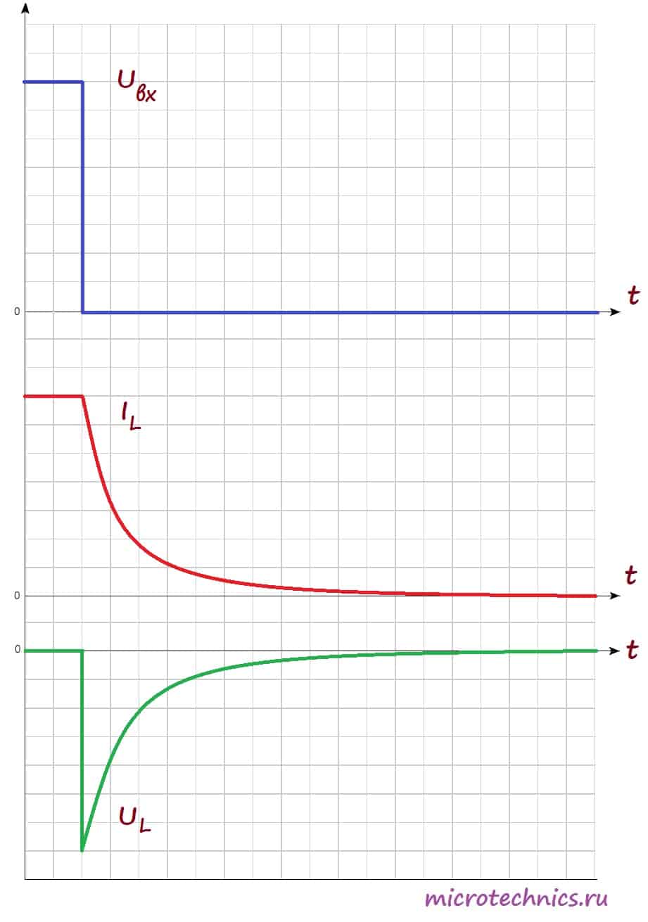
After opening the key, an EMF of self-induction occurs, which prevents the current from decreasing through the coil, so the current does not reach zero immediately, but after some time. The voltage in the coil is identical in form to the case of closing the switch, but opposite in sign. This is due to the fact that the change in current, and, accordingly, the EMF of self-induction in the first and second cases are opposite in sign (in the first case, the current increases, and in the second it decreases).
By the way, I mentioned that the value of the EMF of self-induction is directly proportional to the rate of change in the current strength, and so, the proportionality factor is nothing more than the inductance of the coil:
This concludes with inductors in DC circuits and moves on to AC circuits.
Consider a circuit in which an alternating current is applied to the inductor:

Let's look at the dependences of the current and EMF of self-induction on time, and then we'll figure out why they look like this:

As we have already found out EMF self-induction we have directly proportional and opposite in sign to the rate of change of current:
Actually, the graph demonstrates this dependence to us 🙂 See for yourself - between points 1 and 2, the current changes, and the closer to point 2, the less changes, and at point 2, for some short period of time, the current does not change at all its meaning. Accordingly, the rate of current change is maximum at point 1 and gradually decreases when approaching point 2, and at point 2 it is equal to 0, which we see on EMF diagram of self-induction. Moreover, on the entire interval 1-2, the current increases, which means that the rate of its change is positive, in connection with this, on the EMF, on the whole of this interval, on the contrary, it takes negative values.
Similarly, between points 2 and 3 - the current decreases - the rate of current change is negative and increases - the self-induction EMF increases and is positive. I won’t describe the rest of the graph – all processes follow the same principle there 🙂
In addition, a very important point can be seen on the graph - with an increase in current (sections 1-2 and 3-4), the self-induction EMF and current have different signs (section 1-2: , title="Rendered by QuickLaTeX.com" height="12" width="39" style="vertical-align: 0px;">, участок 3-4: title="Rendered by QuickLaTeX.com" height="12" width="41" style="vertical-align: 0px;">, ). Таким образом, ЭДС самоиндукции препятствует возрастанию тока (индукционные токи направлены “навстречу” току источника). А на участках 2-3 и 4-5 все наоборот – ток убывает, а ЭДС препятствует убыванию тока (поскольку индукционные токи будут направлены в ту же сторону, что и ток источника и будут частично компенсировать уменьшение тока). И в итоге мы приходим к очень интересному факту – катушка индуктивности оказывает сопротивление переменному току, протекающему по цепи. А значит она имеет сопротивление, которое называется индуктивным или реактивным и вычисляется следующим образом:!}
Where is the circular frequency: . - This .
Thus, the higher the frequency of the current, the more resistance the inductor will provide to it. And if the current is constant (= 0), then the reactance of the coil is 0, respectively, it does not affect the flowing current.
Let's go back to our graphs that we built for the case of using an inductor in an AC circuit. We have determined the EMF of the self-induction of the coil, but what will be the voltage? Everything is really simple here 🙂 According to the 2nd Kirchhoff law:
And consequently:
Let's build on one graph the dependences of current and voltage in the circuit on time:

As you can see, current and voltage are phase-shifted () relative to each other, and this is one of the most important properties of AC circuits that use an inductor:
When an inductor is connected to an alternating current circuit, a phase shift appears in the circuit between voltage and current, while the current lags behind the voltage by a quarter of the period.
So we figured out the inclusion of the coil in the AC circuit 🙂
On this, perhaps, we will finish today's article, it turned out to be quite voluminous, so we will talk further about inductors next time. So see you soon, we will be glad to see you on our website!


