A resistor can be described as a passive element of an electrical circuit. Resistors are used primarily to control electrical parameters (voltage and current) in an electrical circuit using the physical property of a resistor called resistance.
There are different types of resistors:
In this article we will discuss in detail the operating principle of a varistor, the connection diagram and the use of a varistor in practice. But, first of all, we must know what a varistor is.
Varistor- this is a special type whose resistance changes under the influence of voltage applied to it. Therefore, it is also called a voltage dependent resistor (VDR). This nonlinear semiconductor element gets its name from the word variable resistor (VARiable resistor).
These varistors are used as a protective device to prevent transient voltage surges in an electrical circuit. A varistor is similar in appearance and size to a capacitor, so it is often confused with it.
In normal operating condition, the varistor has a high resistance. Whenever the transient voltage increases sharply, the resistance of the varistor immediately decreases. Thus, it begins to conduct current through itself, thereby reducing the voltage to a safe level.
There are various types, but metal oxide varistors are the most commonly used in electronic devices. As mentioned above, the main purpose of a varistor in electronic circuits is to protect the circuit from excessive transient voltage surges. These transients typically occur due to static electricity discharge and lightning surges.

The operating principle of a varistor can be easily understood by looking at the resistance versus applied voltage curve.
The graph above shows that during normal operating voltage (say low voltage) its resistance is very high and if the voltage exceeds the rated value of the varistor, then its resistance begins to decrease.

The current-voltage characteristic (volt-ampere characteristic) of the varistor is shown in the figure above. From the figure you can see that a small change in voltage causes a significant change in current.
The voltage level (classification voltage) at which the current flowing through the varistor is 1 mA is the level at which the varistor changes from a non-conducting state to a conducting state. This is because, whenever the applied voltage is greater than or equal to the rated voltage, an avalanche effect occurs, driving the varistor into conduction as a result of reduced resistance.
Thus, even despite the rapid increase in small leakage current, the voltage will be slightly higher than the rated value. Therefore, the varistor will regulate the transient voltage relative to the applied voltage.

The figure above shows examples of the use of a varistor in various power protection systems. Let's consider each case separately.

This circuit represents the protection of a single-phase power line. If transient voltage is supplied from the network to the power terminals of the device, then this surge will reduce the resistance of the varistor and thus protect the electrical circuit.
Varistors(the name is derived from two words Variable Resistors - variable resistance) - these are semiconductor (metal oxide or zinc oxide) resistors that have the property of sharply reducing their resistance from 1000 MOhm to tens of Ohms when the voltage on them increases above a threshold value. In this case, the resistance becomes smaller the greater the voltage applied. The typical current-voltage characteristic of a varistor has a pronounced nonlinear symmetrical shape, i.e. it can also operate on alternating voltage. A varistor must protect electrical equipment connected to the network from overvoltages - this is its main task. Not only short-term high-voltage voltage pulses can appear in the network, but also a long-term increase in voltage up to 380V. In case of long-term overvoltages, for example, when phases are unbalanced when using a welding machine on a different phase, the varistor must withstand the overvoltage and not collapse until the protective device or fuse in front of it is triggered. As the voltage increases, the current through the varistor increases, sharply increasing to the nominal value of the varistor. Electrophysical ceramics are widely used in high voltage electrical engineering. An example of this is varistors - the basis of devices for protecting electrical networks from switching and lightning overvoltages. Zinc oxide varistors (ZOV) are the most popular type. They are made from a polycrystalline multicomponent system, which, along with zinc oxide (Zn0), includes oxides of bismuth (Bi2O3), antimony (Sb2O3), cobalt (Co3O4), manganese (MnO2), chromium (Cr2O3) and a number of other elements.
These are the types of varistors:
varistor 220KD07 (14V)
varistor 270KD07 (17V)
varistor 330KD07 (20V)
varistor 390KD07 (25V)
varistor 560KD07 (35V)
varistor 680KD07 (40V)
varistor 101KD07 (60V)
varistor 121KD07 (75V)
varistor 121KD10 (75V)
varistor 151KD07 (95V)
varistor 151KD10 (95V)
varistor 181KD07 (115V)
varistor 181KD10 (115V)
varistor 221KD10 (140V)
varistor 241KD07 (150V)
varistor 241KD10 (150V)
varistor 241KD14 (150V)
varistor 271KD07 (175V)
varistor 271KD10 (175V)
varistor 301KD14 (200V)
varistor 331KD10 (210V)
varistor 331KD14 (210V)
varistor 361KD10 (230V)
varistor 361KD14 (230V)
varistor 361KD20 (230V)
varistor 391KD07 (250V)
varistor 391KD10 (250V)
varistor 391KD14 (250V)
varistor 391KD20 (250V)
varistor 431KD07 (275V)
varistor 431KD10 (275V)
varistor 431KD14 (275V)
varistor 431KD20 (275V)
varistor 471KD07 (300V)
varistor 471KD10 (300V)
varistor 471KD14 (300V)
varistor 471KD20 (300V)
varistor 561KD14 (350V)
varistor 561KD20 (350V)
varistor 561KD32 (350V)
varistor 621KD10 (385V)
varistor 621KD14 (385V)
varistor 621KD20 (385V)
varistor 681KD14 (420V)
varistor 681KD20 (420V)
varistor 821KD20 (510V)
varistor 102KD20 (625V)
Varistors are installed in parallel with the protected electrical equipment. In the case of a three-phase load, with a star connection, they are connected in each phase between the phase and the ground, and with a delta connection, between the phases. The most preferable location for installing varistors is immediately after the switching device on the side of the protected load. The PROGRESS plant produces a very convenient three-phase surge voltage limiter "Impulse-1", which is a device for fixing varistors on an electrical panel, containing devices placed in a housing - holders for three varistors, equipped with leads. This device allows you to easily implement protection schemes for three-phase loads connected in both star and delta, as well as protect up to three independent electrical installations powered from a single-phase network.
Selecting the type of varistor to use and the determination of its classification voltage is carried out on the basis of an analysis of the operation of the varistor in two modes: in operating mode and in pulse mode.
1. Analysis of the operation of a varistor in operating mode consists of determining from Table 1 such a classification voltage for which the long-term maximum voltage at the load is closest to the table value, but does not exceed it. These tables are valid for varistors with maximum deviations of the classification voltage of no more than 10%. for foreign-made varistors, in most cases it is indicated as part of the marking.
2. Analysis varistor operation in pulse mode consists of calculating the maximum instantaneous energy using the formula:
E=P*tg(phi)/2п*f*n
where E is the maximum instantaneous energy in joules, P is the rated load power per phase (W), f is the frequency of alternating voltage (Hz), n is the efficiency of the protected load. Such calculations are usually performed for loads of several kilowatts or more.
According to Table 2, select the type of varistor that provides energy dissipation, the value of which is calculated using the given formula.
Table 1 In volts
|
maximum permissible continuous AC voltage |
classification voltage |
maximum permissible continuous AC voltage |
maximum permissible continuous continuous voltage |
||
table 2
|
Classification- |
Maximum dissipation energy of varistors, J |
|||||
|
national nap- dressing up, B |
||||||
Just keep in mind that some manufacturers write in varistors classification voltage of the varistor, and some value for alternating current.
On Russian-made varistors, the classification voltage is written.
The main parameters that are used to describe the characteristics of varistors are:
Un - classification voltage, usually measured at a current of 1 mA, is a conditional parameter that is indicated when marking elements;
Um – maximum permissible active variable
voltage (rms);
Um= - maximum permissible direct voltage;
P is the rated average power dissipation, this is the one that the varistor can dissipate during its entire service life while maintaining the parameters within the established limits;
W is the maximum permissible absorbed energy in joules (J) when exposed to a single pulse. This value determines how long the overload can last (with maximum power Рт) without the danger of damaging the varistor.
The voltage rating determines the maximum possible voltage that can be applied to the varistor. Only a short overvoltage pulse can exceed the rated voltage, namely the overload current (pulse) Imax and the pulse energy Wmax. When a varistor operates, the amplitude and number of pulses are applied to it, which is a characteristic of standard pulse shapes.
Wmax is the energy that is dissipated by a varistor when a 10/1000 current pulse flows through it. The Pmax characteristic should be taken into account when the varistor cannot cope with heat dissipation in pauses between applied current pulses and overheats. In general, Pmax depends on the size and design of the varistor leads.
Designation of varistors:
The number before the letters is the diameter of the varistor in mm. The numbers after the letters are the voltage 431 = 430V, 471 = 470V. It happens that markings are often written without letters. Type 7271, 10751.
Examples: protection against voltage surges in the HBOX-360 UPS from England where there is 240V, there were 2 varistors in parallel at 431 (430V).
The varistor in the 120V UPS from the WII game console from the USA was 7Z271 at 270V.
The varistor in the 220V UPS from the DVD player for Russia was 10Z471 at 470V.
The varistor in the 220V UPS from the Samsung 21" CRT TV was TVR10751 (750V).
The typical response time of varistors when exposed to overvoltage is no more than 25 ns, but it may not be enough to protect some types of equipment (no more than 1 ns is needed for electrostatic protection). Therefore, the improvement of varistor manufacturing technology around the world is aimed at increasing their performance. For example, the company “S+M Epcos”, thanks to the use in the manufacture of varistors of the multilayer structure SIOV-CN and their SMD design (leadless design for surface mounting), is able to achieve a response time of less than 0.5 ns (when such elements are located on To obtain the specified speed, the printed circuit board already needs to minimize the inductance of the external connecting conductors). In the disk design of varistors, due to the inductance of the leads, the response time increases to several nanoseconds.
For a network with an effective voltage of 220 V (50 Hz), varistors with a classification voltage of at least 380...430 V are usually installed. For a varistor with a classification voltage of 430 V, with a current pulse of 100 A, the voltage will be limited to about 600 V.
Varistors can be connected in series or parallel, their resistance is nonlinear, the voltage between them will equalize itself. In fact, a varistor can be considered a two-way (polarity-dependent) zener diode, only with a softer characteristic. For example, you need to get a 360V varistor, for this we take two 180V each and connect them in series! To increase the power of a varistor from several small ones, you can get a powerful assembly by connecting them in parallel, however, it must be taken into account that there is a certain spread in the classification voltage parameters of each varistor from the assembly, so the use of one more powerful varistor is more preferable. To ensure normal parallel operation of varistors, a strict coincidence of the current-voltage characteristics is necessary. This problem is completely solvable with a series-parallel connection circuit - i.e. varistors are assembled in series into pillars, and the pillars are connected in parallel. In this case, by selecting varistors, the coincidence of the I-V characteristics of the varistor columns is ensured. This is what they do when creating high-voltage, powerful surge suppressors (OSS).
A common cause of equipment failure, such as power supplies, is the presence of overvoltage pulses in the network. They can be caused by various electromagnetic interference associated with lightning discharges, or with switching and discharges of inductive and capacitive circuit elements, as well as corresponding transient processes.
![]() Varistors- a reliable means for surge suppression in primary electrical circuits. Company Littelfuse produces a wide range of these products, consisting of several series, including industry leaders in energy dissipation, industrial varistors of the series C-III.
Varistors- a reliable means for surge suppression in primary electrical circuits. Company Littelfuse produces a wide range of these products, consisting of several series, including industry leaders in energy dissipation, industrial varistors of the series C-III.
To be confident in the reliable functioning of the device being developed, it is necessary to think about suppression of voltage surges at the early stages of development. This can be a complex task because electronic components are very sensitive to transients. The designer must determine the type of hazard that could cause power surges and what standards the device must meet based on its application. Varistors are most often used to suppress voltage surges in primary circuits. There are many varistor manufacturing companies on the market. Let's look at different types of varistors, dwell on their physical essence and compare varistors from the leader in the protective components market - the company Littelfuse– with varistors from other popular manufacturers – Epcos And Fenghua.
A varistor is an electronic device whose resistance changes nonlinearly with changes in the voltage supplied to it; its current-voltage characteristic (CV) is similar to the current-voltage characteristic of bidirectional Zener diodes. The varistor consists mainly of zinc oxide ZNO with small amounts of bismuth, cobalt, magnesium and other elements. A Metal Oxide Varistor (MOV) is sintered during the manufacturing process into a ceramic semiconductor with a crystalline microstructure that allows very large energies to be dissipated, which is why varistors are often used to protect against voltage surges caused by lightning strikes, transients, and inductives. loads, electrostatic discharges in AC and DC circuits, as well as in industrial power lines. In addition, varistors are used in constant voltage networks, such as low-voltage power supplies or automotive circuits. The production process of varistors allows them to be given a variety of shapes. However, the most common form factor of varistors is a disk with radial leads.
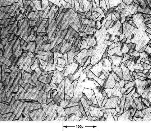
The varistor body is an isotropic granular structure of zinc oxide ZnO (Figure 1). The granules are separated from each other, and their separation boundary has a current-voltage characteristic similar to a pn junction in semiconductors. These boundaries at low voltages have very low conductivity, which increases nonlinearly with increasing voltage across the varistor.
A symmetrical current-voltage characteristic is shown in Figure 2. Thanks to it, the varistor does an excellent job of suppressing voltage surges. When they appear in the circuit, the resistance of the varistor decreases many times: from an almost non-conducting state to a highly conductive state, reducing the voltage pulse to a value safe for the circuit. Thus, the energy of the input voltage pulse, potentially dangerous to the circuit elements, is absorbed by the varistor and protects components sensitive to voltage surges.

At the points of contact between the varistor microbeads, a conduction effect occurs. Since the number of granules in the volume of the varistor is very large, the energy absorbed by the varistor significantly exceeds the energy that can pass through a single p-n junction in Zener diodes. During the passage of current through the varistor, the entire passing charge is evenly distributed throughout the entire volume. Thus, the amount of energy that a varistor can absorb directly depends on its volume. The operating voltage of the varistor and the maximum current depend on the distance between the electrodes, between which there are zinc oxide granules. However, there are many other technological aspects that determine these electrical parameters: granulation and sintering technology, which affects the size of the granules and their contact area, connection of metal leads, varistor coating, alloying additives. For example, the operating temperature range of disk varistors depends on the type of disk coating: for epoxy-coated varistors the range is -55...85 ° C, for a phenol coating, found in Littelfuse series varistors C-III, this range has been extended to 125°C. Also, most series of surface-mount varistors have an extended operating temperature range.
Let's take a closer look at the operating principle of a varistor.
In its body, between the metal contacts, there are granules with an average size d (Figure 3).

Rice. 3. Schematic representation of the microstructure of a metal oxide varistor
Conductive zinc oxide granules with an average granule size d are separated from each other by intergranular boundaries.
When designing a varistor for a given rated voltage Vn, the main parameter is the number of granules n contained between the contacts, which in turn affects the size of the varistor. In practice, its material is characterized by a voltage gradient V/mm, measured in a collinear direction with the normal to the plane of the varistor. To control the composition and production conditions, the gradient must be constant. Since the physical dimensions of a varistor have certain limits, the combination of impurities in the device makes it possible to achieve a given granule size and the desired result.
A fundamental property of a ZnO varistor is its almost constant voltage drop at the grain boundaries throughout the entire volume. Observations show that, regardless of the type of varistor, the voltage drop at the contact boundary of the granules is always 2...3 V. The voltage drop at the boundaries of the granules does not depend on the size of the granules themselves. Thus, if we omit the different methods of production and alloying of zinc oxide, the voltage of the varistor will depend on its thickness and the size of the granules. This dependence can be easily expressed in the following form (formula 1):
where d is the average granule size.
Considering
 ,
,
we obtain the data presented in table 1.
Table 1. Dependence of varistor structural parameters on voltage
Varistor voltage Vn– this is the voltage on the current-voltage characteristic, where a transition occurs from a low-conducting state in the linear section of the graph to the nonlinear mode of a highly conductive state. By general agreement, a current of 1 mA was chosen to standardize measurements.
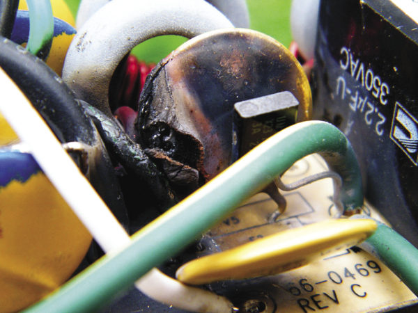
Although varistors can absorb large amounts of energy in a few microseconds, they cannot remain conducting for long. Therefore, in some cases, when, for example, the voltage in the network increases for a long time to the trigger level, the varistor begins to get very hot. Its overheating may result in fire (Figure 4). To protect against this, thermistors were used. A varistor with a built-in thermistor is protected from overheating, which prolongs its service life and protects the device from possible fire.
Let us conduct a comparative analysis of the most popular varistors produced by Littelfuse, Epcos and Fenghua with operating voltages of 250 and 275 V (AC rms) and disk diameters of 10, 14 and 20 mm.
As can be seen from Table 2, the energy dissipated by a varistor depends not only on its size, but also on the production technology and materials used to produce the series. Please note that the industrial grade series C-III produced by Littelfuse took first place, the series UltraMOV also showed very high performance, being at the level of its competitors - the series Advanced production Epcos. It can also be noted that C-III varistors, with a smaller size (D = 14 mm), have greater energy dissipation than the standard series of competitors, which have larger dimensions (D = 20 mm), and the difference in energy dissipation between high-quality varistors in the housing is D = 20 mm and standard varistors in housing D = 10 mm can differ by an order of magnitude.
Table 2. Comparative analysis of the most popular varistors produced by Littelfuse, Epcos and Fenghua
| Name | Manufacturer | Series | D, mm | VRMS, V | Imax (8/20 µs), A | Wmax (2 ms), J |
| Littelfuse | C-III | 20 | 275 | 10000 | 320 | |
| Littelfuse | C-III | 20 | 250 | 10000 | 300 | |
| , | Epcos | AdvanceD | 20 | 275 | 10000 | 215 |
| , | Epcos | AdvanceD | 20 | 250 | 10000 | 195 |
| Littelfuse | UltraMOV® | 20 | 275 | 6500 | 190 | |
| Littelfuse | UltraMOV® | 20 | 250 | 6500 | 170 | |
| , | Epcos | StandarD | 20 | 275 | 8000 | 151 |
| Littelfuse | C-III | 14 | 275 | 6500 | 145 | |
| Fenghua | General | 20 | 275 | 6500 | 140 | |
| , | Epcos | StandarD | 20 | 250 | 8000 | 140 |
| Littelfuse | C-III | 14 | 250 | 6500 | 135 | |
| Fenghua | General | 20 | 250 | 6500 | 130 | |
| , | Epcos | AdvanceD | 14 | 275 | 6000 | 110 |
| Littelfuse | UltraMOV® | 14 | 275 | 4500 | 110 | |
| , | Epcos | AdvanceD | 14 | 250 | 6000 | 100 |
| Littelfuse | UltraMOV® | 14 | 250 | 4500 | 100 | |
| Fenghua | General | 14 | 275 | 4500 | 75 | |
| , | Epcos | StandarD | 14 | 275 | 4500 | 71 |
| Fenghua | General | 14 | 250 | 4500 | 70 | |
| Littelfuse | C-III | 10 | 275 | 3500 | 70 | |
| , | Epcos | StandarD | 14 | 250 | 4500 | 65 |
| Littelfuse | C-III | 10 | 250 | 3500 | 60 | |
| , | Epcos | AdvanceD | 10 | 275 | 3500 | 55 |
| Littelfuse | UltraMOV® | 10 | 275 | 2500 | 55 | |
| , | Epcos | AdvanceD | 10 | 250 | 3500 | 50 |
| Littelfuse | UltraMOV® | 10 | 250 | 2500 | 50 | |
| Fenghua | General | 10 | 275 | 2500 | 45 | |
| , | Epcos | StandarD | 10 | 275 | 2500 | 43 |
| Fenghua | General | 10 | 250 | 2500 | 40 | |
| , | Epcos | StandarD | 10 | 250 | 2500 | 38 |
An overview of varistors produced by Littelfuse, broken down into series and areas of application, is presented in Table 3.
Table 3. Application areas of Littelfuse varistors
| Segment | Typical Applications and Examples | Series | Technology | SMD mounting |
| Low voltage equipment, single board devices | Handheld and handheld devices, controllers, measurement equipment, computers, remote sensors, I/O ports and interfaces, medical equipment | CH | MOV | + |
| MA, ZA, RA, UltraMOV, CIII | MOV | |||
| ML, MLE, MLN, MHS | MLV | + | ||
| Electrical networks, surge protectors | Uninterruptible power supplies, power meters, AC power supplies, LED drivers, power supplies, industrial power supplies, circuit breakers, surge protectors, consumer electronics, power management | TMOV, UltraMOV, CIII, LA, HA, HB, HG, HF, DHB, TMOV34S, RA | MOV | – |
| SM20, SM7, CH | MOV | + | ||
| Automotive electronics | ABS, data buses, motor controllers, servos, airbags, control of mirrors, power windows, brushes | SM7,CH | MOV | – |
| ZA, LV UltraMOV | MOV | – | ||
| AUML, ML, MLE, MLN, MHS | MLV | + | ||
| Telecommunications equipment | Cellular and DECT phones, routers, modems, network cards, subscriber equipment protection, T1/E1/ISDN, data bus protection | SM7,CH | MOV | – |
| ZA, LV UltraMOV | MOV | – | ||
| SM20, SM7, ML, MLE, MLN, MHS | MLV | + | ||
| Powerful industrial equipment | Power relays, solenoids, motor drivers, power supplies, robots, large motors/pumps/compressors | DA/DB, BA/BB, CA, HA, HB, HC, HG, HF, DHB, TMOV34S, CIII, UltraMOV | MOV | – |
The properties of semiconductors to change their electrical conductivity under the influence of external excitations is used in the construction of a number of simple semiconductor devices (junctionless), the so-called semiconductor resistors.
Semiconductor resistors are many types of resistors made from various semiconductor materials and using the dependence of their electrical resistance on various factors affecting the resistor. Accordingly, they distinguish:
varistors (dependence of R on voltage U);
thermistors (depending on temperature T);
photoresistors (from the luminous flux F);
magnetoresistors (from magnetic field B);
strain gauges (from mechanical pressure P).
Symbols for semiconductor resistors are shown in Fig. 1.
The presence of semiconductor resistors with such a wide range of dependencies allows them to be used in electronic equipment being developed to solve many different problems:
as sensors for measuring the corresponding parameter (U, T, F, V, P);
in devices for stabilizing object parameters;
in alarm systems and overload protection;
in systems for regulating physical quantities;
in signal conversion systems.
A varistor is a semiconductor resistor whose resistance nonlinearly depends on the applied voltage, both positive and negative. The varistor has two terminals.
Currently, varistors are quite widely used, primarily as overvoltage protection elements; moreover, due to the symmetry of the highly nonlinear current-voltage characteristic with a uniquely high pulse stability, oxide-semiconductor varistors are currently practically the only real and widespread fast-acting means of protecting complex and expensive semiconductor systems for various purposes.
The current-voltage characteristic (CVC) of the varistor is nonlinear and symmetrical (Fig. 2).

Rice. 2. Volt-ampere characteristic of the varistor
The main materials used to make varistors are silicon carbide and zinc oxide.
To get this kind of addiction I(U) varistors are made mainly from silicon carbide SiC, powdered grains of which 20 ... 180 microns in size are mixed with 10 ... 40% of a dielectric binder material - clay, ceramics, pressed and fired at high temperatures. As a result, the varistor inside is a conglomerate of grains with very different sizes of gaps and contact areas.
The nonlinearity of the current-voltage characteristic of this type of varistor is due to an increase in the conductivity of surface potential barriers or oxide films on crystals in strong electric fields. And also an increase in the conductivity of point contacts between crystals due to heating due to the power released on them.
Since the thickness of the surface potential barriers and oxide films on silicon carbide crystals is small, strong electric fields can arise there even at low varistor voltages, which leads to charge carrier tunneling through the potential barriers or through thin oxide films. Thus, at low voltages on the varistor, the nonlinearity of the current-voltage characteristic is associated with the dependence of the conductivity of surface potential barriers and oxide films on the voltage value.
At high voltages across the varistor and, accordingly, at high currents passing through the varistor, the current density in the point contacts turns out to be very high. All voltage applied to the varistor drops at the point contacts. Therefore, the specific power released in point contacts reaches values that cannot be ignored. Heating of point contacts leads to a decrease in their resistance and to nonlinearity of the current-voltage characteristic.
With a fine-grained structure, these mechanisms are practically independent of the polarity of the applied voltage - accordingly, the current-voltage characteristic of the varistor turns out to be symmetrical.
The resistance of point contacts is determined by the spreading resistance, i.e. the resistance of small active regions of the semiconductor under the point contacts. Due to the smallness of the active areas, their heating practically does not lead to an increase in the temperature of the entire varistor. In addition, small volumes of active regions ensure low inertia of thermal processes. Theoretical calculations show that the thermal time constant of active regions can be 10.6...1.7 s. Considering the heating of active regions to be one of the main processes leading to nonlinearity of the current-voltage characteristic in the operating range of voltages and currents for a varistor, a number of important dependencies and characteristics of the varistor can be obtained.
The temperature dependence of the conductivity of semiconductors corresponds to the equation:  .
.
Spreading resistance of two contacting crystals:  ,
,
Where d– point contact diameter, B– coefficient of temperature sensitivity of the surface layers of the crystal.
Then the static resistance of the varistor, consisting of N parallel connected chains having their own turn N’ series-connected contacting crystals:  .
.
Thermal balance equation for the active regions of the varistor:
Where N– scattering coefficient of active regions, T– temperature of active regions, T– temperature of the environment surrounding the active regions.
The current-voltage characteristic can be approximately represented by the equations:
 ,
, ,
,
Where U,I– varistor voltage and current, C,B,
 ,
,
 – some coefficients, and
  ,
, .
.
Parameters and characteristics of varistors based on silicon carbide
Nonlinearity coefficient  characterizes the nonlinearity of the current-voltage characteristic of the varistor. For linear resistors it is equal to unity, for nonlinear resistors it is significantly more than one, and with increasing
  the nonlinearity of the current-voltage characteristic increases. The expression for calculating the nonlinearity coefficient can be obtained from the relationship between the static and dynamic resistances of the varistor at a certain point of the current-voltage characteristic:
 .
.
I-V characteristic of a varistor on a double logarithmic scale (Fig. 3):
lg U=lg I+lg C
EMBED Word.Picture.8 
Rice. 3. I-V characteristics of a varistor on a double logarithmic scale
The nonlinearity coefficient in this case will be numerically equal to the cotangent of the angle of inclination of the characteristic to the current axis: β = ctg  = (log I 2 - lg I 1)/(lg U 2 -lg U 1).
To calculate the dependence of the varistor resistance on the current flowing through it or the applied voltage, use the following relationship:
R =C.I.α-1/ B
Sometimes in practical calculations it is inconvenient to use analytical expressions of the current-voltage characteristic. In this case, over a fairly wide range of voltages, you can use the empirical equation:  ,
,
Where  – electrical conductivity of the varistor working fluid in weak fields, a– constant. The current-voltage characteristic of the varistor is shown in Fig. 2.
Then the nonlinearity coefficient β and constant B will take the following form:
 ,
, .
.
The calculated dependences of β on external voltage are presented in Fig. 4.

Rice. 4. Calculated dependence of the nonlinearity coefficient on voltage at various temperatures (V = 600 K)
Varistor series 07K, 10K, 14K, 20K– a zinc oxide protective element that has the ability to instantly change its own resistance under the influence of the applied voltage. Characteristic pronounced nonlinear and symmetrical current-voltage characteristics provide the ability to operate varistors in DC, AC and pulsed current circuits.
Principle of operation varistor lies in its ability in a matter of nanoseconds (up to 25 ns) reduce its own resistance to a level of several ohms when exposed to a voltage exceeding the nominal value - the response voltage, operating current it can reach 100A.
In the normal state, the varistor resistance reaches several hundred MOhms, and since varistors are connected parallel to the circuit, then no current passes through it and it acts as a dielectric. A pulse jump activates the varistor, lowering its resistance - a short circuit occurs and the fuse, which must be installed in front of the varistor, blows, and the circuit opens.
At the moment of operation, the excess load is shunted, absorbed energy(before 282 J with a current pulse 2.5 ms) is dissipated in the form of thermal radiation. The overall dimensions of the varistor play a significant role in this case - the total surface area of the varistor has a proportional effect on the ability to dampen a voltage pulse without destroying the device itself.
Varistors series 07K, 10K, 14K, 20K have a disk shape(disk varistors) of various thicknesses with unidirectional radial type wire leads. The presented varistors are manufactured using the pressing method powdered zinc oxide(ZnO).
The varistor housing is marked with the rated classification voltage and the corresponding voltage tolerance ( ±10%). On samples of imported varistors, when marking the tolerance, a symbolic designation is used, for example, the letter K indicates a tolerance of ±10%, the letter M indicates a tolerance of ±20%.
Varistors are installed parallel to the protected device by soldering leads. To achieve the maximum level of protection, it is recommended to use two identical varistors connected in parallel to each other and an additional fuse installed in series before the varistors.
Apply provided varistors 07K, 10K, 14K, 20K to protect elements from overvoltage in power supplies and systems, household and military equipment, telecommunications and measuring equipment.
Detailed characteristics, identification of markings, overall dimensions, general design of varistors 07K, 10K, 14K, 20K are listed below. Our company guarantees the quality and performance of varistors for 2 years from the date of purchase; Quality certificates are provided.
The final price for zinc oxide varistors 07K, 10K, 14K, 20K depends on the quantity, delivery time and form of payment.


